
Receiver plate with multiple cross-sections

a technology of receiving plate and cross-section, which is applied in the direction of analytical using chemical indicators, laboratory glassware, instruments, etc., can solve the problems of non-uniform gap and form non-uniform cross-section along the well height, and achieve the effect of reducing wicking and cross-contamination, increasing the volume around the filter, and increasing the gap siz

Active Publication Date: 2006-11-23
MILLIPORE CORP
View PDF8 Cites 14 Cited by
  • Summary
  • Abstract
  • Description
  • Claims
  • Application Information

AI Technical Summary

Benefits of technology

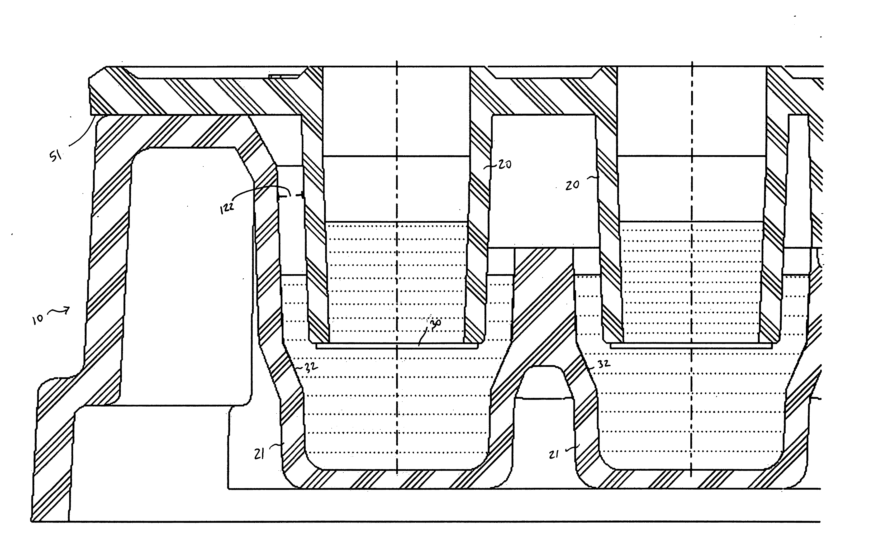
[0013] The problems of the prior art have been overcome by the present invention, which provides a multi-well assembly including a filter plate and a receiver plate. Each plate includes a plurality of wells, which, when the filter plate is placed in a nesting relationship with the receiver plate, each filter plate well has a corresponding receiver plate well into which it extends in nesting relationship. The receiver plate wells are of a non-uniform cross section along the height of the well. The cross-section of the upper portion of the receiver plate well is chosen to increase the gap between the outer walls of the filter plate wells and the inner walls of a corresponding receiver plate well when the receiver plate and filter plate are in a nesting relationship. This cross section creates a non-uniform gap such that the increased gap size reduces wicking and cross-contamination as well as increases the volume around the filter well to accommodate larger media volume variations. The lower portion of the receiver plate well has a reduced cross section compared to the upper portion, thus forming a non-uniform cross-section along the well height. This reduced volume lower section reduces the media required for the experiment. In a preferred embodiment, the cross-section of the receiver plate wells transitions from a square cross-section to a round cross-section. Preferably the portion of each receiver plate well that accommodates the filter plate well is square or substantially square in cross-section, and transitions to a circular or other geometric cross-section just below where the membrane on the filter plate well would be positioned when the filter plate is in nesting relationship with the receiver plate. The square cross-section also provides larger pathways for air to escape during assembly of the device. A square cross section maximizes the useable space between neighboring wells given a circular filter well and the limitations of ANSI / SBS restrictions on well spacing. A multi-section well of maximum cross-section in an upper region and a minimized cross-section in a lower region, with a gradual transition between the regions, is thus provided.
[0014] The multi-well assembly of the present invention also improves the repeatability of positioning the filter plate and receiver plate in proper nesting relationship, so that the filter wells are not eccentric with the receiver wells. The present invention also provides a means to improve automated assembly and disassembly by means of a lead-in feature. In addition, evaporation of media from the receiver wells is reduced by providing a flat surface-to-surface contact between the filter plate and receiver plate.

Problems solved by technology

This cross section creates a non-uniform gap such that the increased gap size reduces wicking and cross-contamination as well as increases the volume around the filter well to accommodate larger media volume variations.
The lower portion of the receiver plate well has a reduced cross section compared to the upper portion, thus forming a non-uniform cross-section along the well height.

Method used


Image

  • Receiver plate with multiple cross-sections
  • Receiver plate with multiple cross-sections
  • Receiver plate with multiple cross-sections

Examples


Embodiment Construction

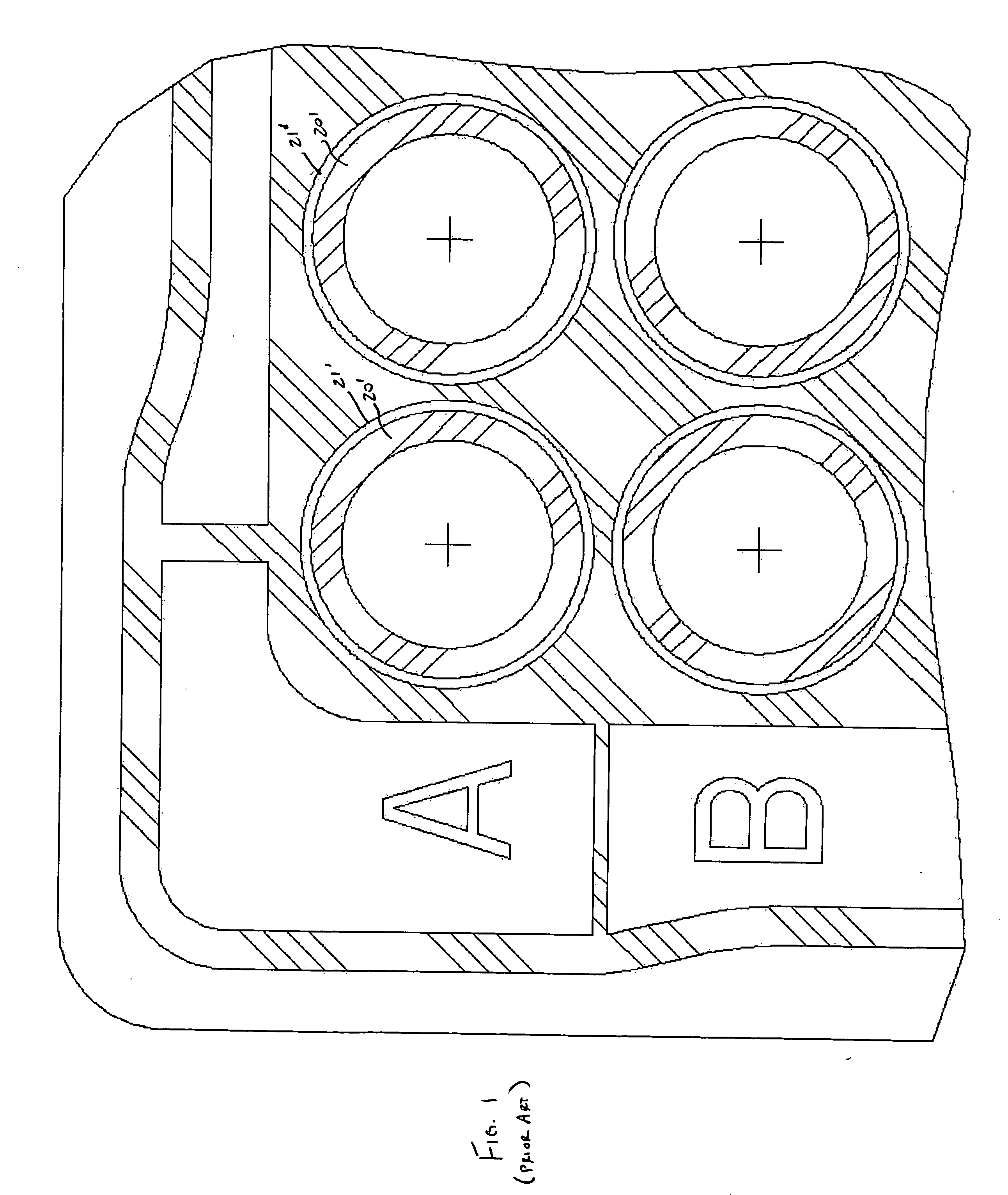
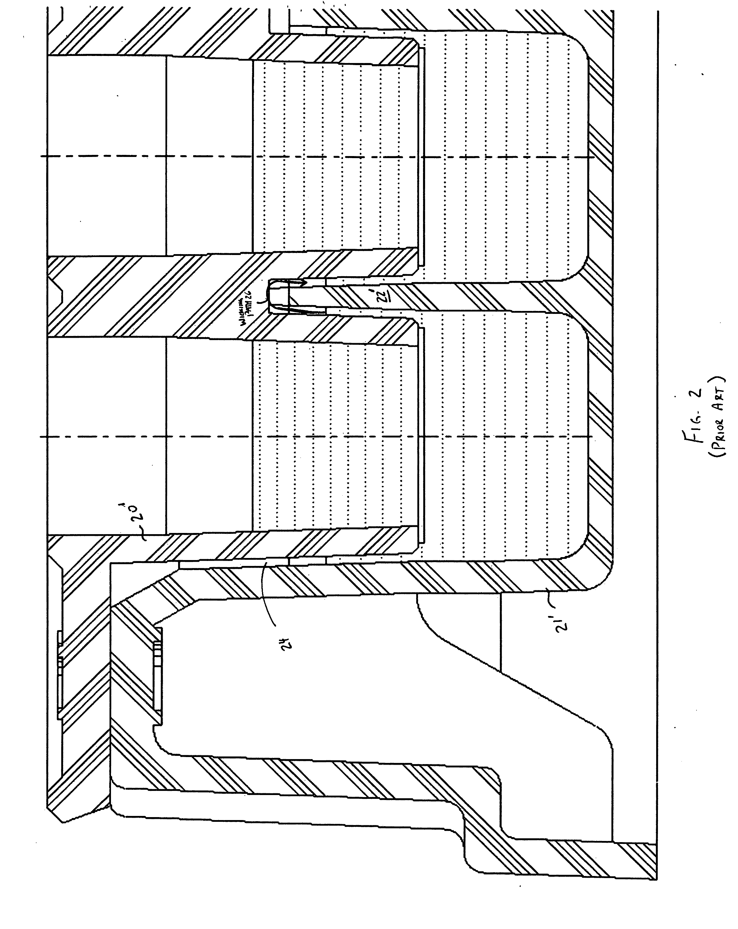
[0022] Turning first to FIGS. 1 and 2, there is shown conventional filter plate wells 20′ nested in conventional receiver plate wells 21′. The filter plate wells 20′ have a uniform circular cross-section, and the receiver plate wells 21′ have a uniform circular cross-section as well. The outside diameter of the filter plate wells 20′ is slightly smaller than the inside diameter of the receiver plate wells 21′, enabling the filter plate wells 20′ to be nested within the receiver plate wells as seen in FIG. 2. A small capillary gap 24 is formed between the outer walls of the filter plate wells 20′ and the inner walls of the corresponding receiver plate wells 21′, as well as between the inner walls of the filter plate wells 20′ and the wall 22′ separating receiver plate wells 21′. This gap allows for displacement and wicking of fluid and results in cross-contamination, as fluid from one receiver plate well can travel in the gap and contaminate fluid in another well, as shown by the wic...


PUM

PropertyMeasurementUnit
anglesaaaaaaaaaa
angleaaaaaaaaaa
diameteraaaaaaaaaa

Abstract

A multi-well assembly including a filter plate and receiver plate. Each plate includes a plurality of wells, which, when the filter plate is placed in nesting relationship with the receiver plate, each filter plate well has a corresponding receiver plate well into which it extends. The receiver plate wells are of a non-uniform cross-section in order to increase the gap between the outer walls of the filter plate wells and the inner walls of a corresponding receiver plate well when the receiver plate and filter plate are in nesting relationship. The increased gap size reduces wicking and cross-contamination. A multi-section well of maximum cross-section in an upper region and a minimized cross-section in a lower region, with a gradual transition between the regions, is thus provided. The multi-well assembly of the present invention also improves the repeatability of positioning the filter plate and receiver plate in proper nesting relationship and provides stability during handling, mixing and shaking operations.

Description

BACKGROUND OF THE INVENTION [0001] The bioavailability of a drug is affected by a number of factors including its ability to be absorbed into the blood stream through the cells lining the intestines. There are a number of different in vitro assay options available to predict the gastrointestinal absorption property of drugs including a permeability assay, and a method known as PAMPA (Parallel Artificial Membrane Permeability Assay), which uses a lipid filled membrane to simulate the lipid bilayer of various cell types, including intestinal epithelium. These non-cell based permeability assays are automation compatible, relatively fast (4-24 hours), inexpensive, and straightforward. They are being used with increasing frequency to determine the passive, transcellular permeability properties of potential drug compounds. The majority of drugs enter the blood stream by passive diffusion through the intestinal epithelium. Consequently, permeability assays that measure passive transport th...

Claims


Application Information

Patent Timeline
Patent Type & Authority Applications(United States)
IPC IPC(8): C12M1/34C12M1/12B01L11/00B01L99/00
CPCB01L3/50255B01L3/5085B01L2200/025B01L2200/0684B01L2300/0681B01L2300/0829B01L2300/0858B01L2200/0678B01L2200/141G01N1/00G01N33/48
Inventor SCOTT, CHRISTOPHER A.FOLEY, BRIAN
Owner MILLIPORE CORP
Learn More