Shock improvement ramp for load/unload mechanism and magnetic disk drive

Inactive Publication Date: 2006-11-23
WESTERN DIGITAL TECH INC
View PDF6 Cites 10 Cited by
  • Summary
  • Abstract
  • Description
  • Claims
  • Application Information

AI Technical Summary

Benefits of technology

[0013] The counter surface will not be chipped by the peripheral edge because the relief space around the peripheral edge of the recording surface prevents the peripheral edge from coming into contact with the recording surface when the peripheral side surface is shifted toward the counter surface. This relief space is particularly effective for a magnetic disk drive in which the peripheral side surface may be displaced and may come into contact with the counter surface while the magnetic disk is rotating. The relief space is effective in controlling the production of particles if the recording surface comes into contact with the counter surface before the peripheral edge comes into contact with the counter surface when the peripheral side surface is shifted greatly because the ability of the recording surface to chip the counter surface is less than that of the peripheral edge.
[0014] The relief space may be formed by sinking a predetermined area, containing an orthogonal projection of the peripheral side surface, on the counter surface below the level of an area of the counter surface nearer to the recording surface than the predetermined area. The size of the predetermined area is determined selectively such that contact between the peripheral side surface or the peripheral edge and the counter surface can be prevented when the peripheral side surface is shifted toward the counter surface. The relief space may be formed by forming a groove and a slope in the counter surface. The recessed predetermined area or the groove is effective even if the recessed predetermined area or the groove has a small width when the recessed predetermined area or the groove has a shape resembling a circular arc. The reduction of the strength of the ramp can be prevented when the recessed predetermined area or the groove has the small width.

Problems solved by technology

If the magnetic disk collides against or comes into contact with the ramp, the surface of the magnetic disk is scratched or the ramp is damaged and, consequently, particles may be produced.
Consequently, the production of particles due to contact or collision between the magnetic disk and the ramp, particularly the production of particles due to collision between the rotating magnetic disk and the ramp while the magnetic disk is rotating, cannot be satisfactorily controlled.

Method used


Image

  • Shock improvement ramp for load/unload mechanism and magnetic disk drive
  • Shock improvement ramp for load/unload mechanism and magnetic disk drive
  • Shock improvement ramp for load/unload mechanism and magnetic disk drive

Examples


Embodiment Construction

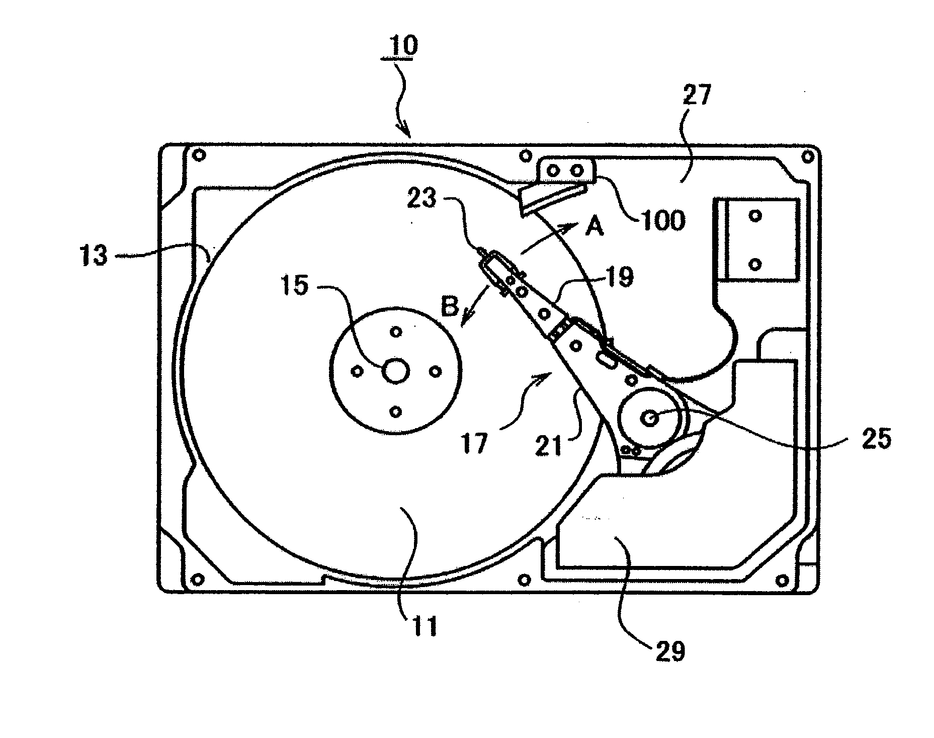
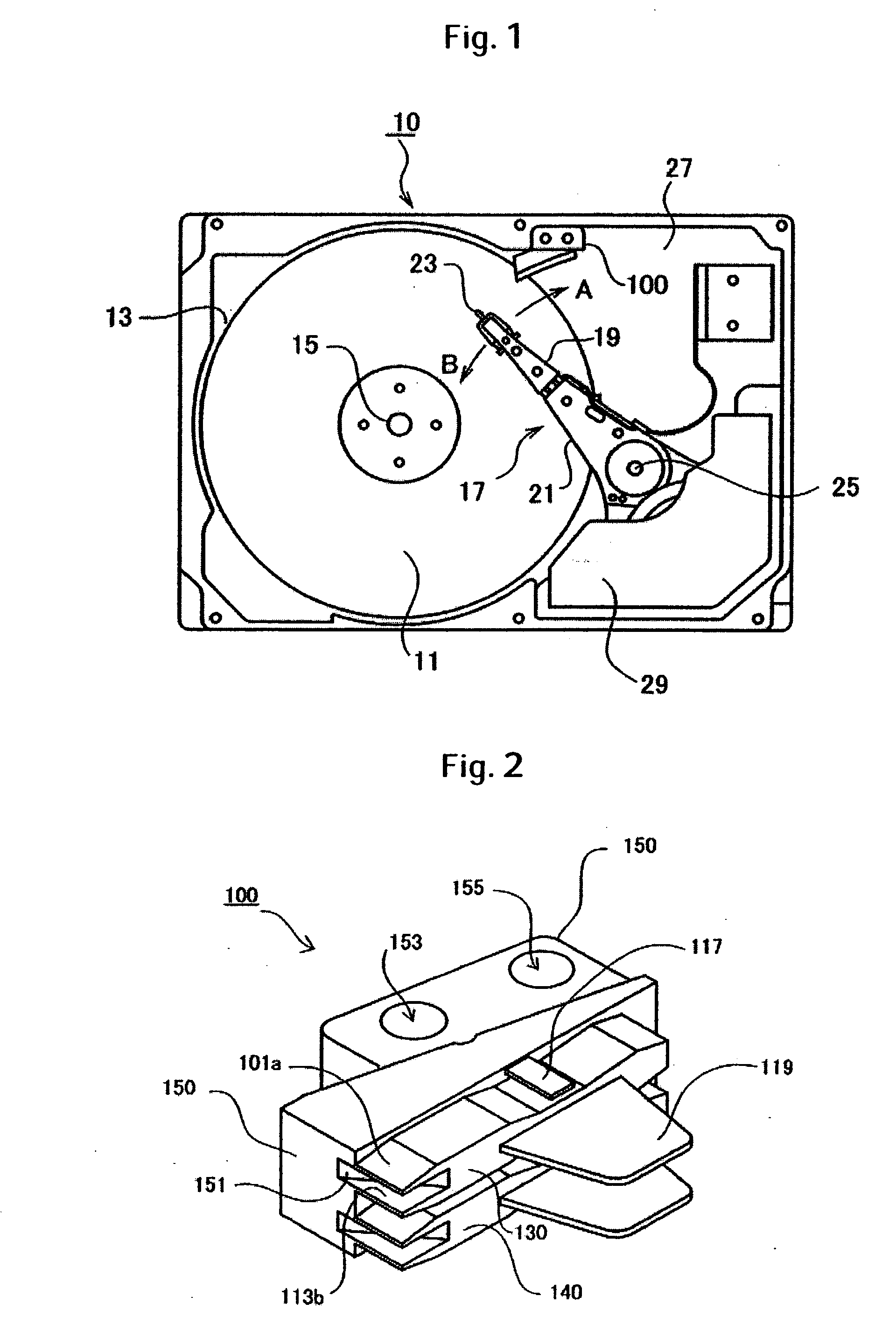
[0028]FIG. 1 is a plan view of a magnetic disk drive 10 in an exemplary embodiment according to the present invention. Magnetic disks 11 are supported for rotation on a spindle shaft 15. A spindle motor attached to a base 27 rotates the spindle shaft 15. The two magnetic disks 11 are separated by a predetermined vertical space. The two magnetic disks 11 rotate together on the spindle shaft 15. The two magnetic disks 11 are the same in construction and each of the magnetic disks 11 has opposite recording surfaces.

[0029] A head support mechanism 17 includes an HGA 19 and an actuator assembly 21. The HGA 19 includes a suspension assembly having a flexure and a load beam, and a head slider attached to the flexure. A lifting tab 23 is formed on the tip of the HGA 19. The lifting tab 23 slides on the slide surface of a ramp 100. The HGA 19 is attached to the actuator assembly 21. Four HGAs 19 are disposed with predetermined intervals in association with the four recording surfaces of the...


PUM


Abstract

Embodiments of the invention prevent contact between a peripheral edge of a magnetic disk and a counter surface of a ramp when the magnetic disk is displaced. In one embodiment, a ramp is disposed near the peripheral side surface of a magnetic disk. The ramp has magnetic disk retainers each having slide surfaces and counter surfaces respectively facing the recording surfaces of the magnetic disk. Grooves or recesses are formed in the counter surfaces to define relief spaces. When the peripheral side surface of the magnetic disk is displaced toward the counter surface by shocks exerted on the magnetic disk drive, the relief space prevents the peripheral edge from coming into contact with the counter surface. Thus the amount of particles produced by the collision of the magnetic disk with the ramp can be reduced.

Description

CROSS-REFERENCES TO RELATED APPLICATIONS [0001] This application claims priority from Japanese Patent Application No. JP2005-146723, filed May 19, 2005, the entire disclosure of which is incorporated herein by reference. BACKGROUND OF THE INVENTION [0002] The present invention relates to a load / unload mechanism that reduces dust for a magnetic disk drive. [0003] A head slider included in a magnetic disk drive is caused to fly over the surface of a magnetic disk by the pressure of air currents produced by the rotating magnetic disk acting on its air bearing surface. A rotary actuator rotatably supporting the head slider carries the head slider in a direction substantially parallel to the radius of the magnetic disk to locate the head slider at a position corresponding to a predetermined track. Most magnetic disk drives employ a load / unload mechanism for retracting the head slider to a home position while the magnetic disk drives are stopping or while a recording or a reproducing oper...

Claims


Application Information

Patent Timeline
IPC IPC(8): G11B15/18
CPCG11B5/54
Inventor OKADA, TAKAHISAHIRAMATSU, TOMOKITAKAHASHI, KOHJIWATANABE, KATSUYA
Owner WESTERN DIGITAL TECH INC
Why Eureka
Try Eureka