
Linear light beam generating optical system

a light beam and optical system technology, applied in semiconductor lasers, lighting and heating equipment, instruments, etc., can solve the problems of difficult to obtain a high output power semiconductor laser, inability to obtain a projecting light having a sufficient power, and difficult to project onto a large area, etc., to achieve low cost and simple structure of optical systems, the effect of uniform light intensity

Inactive Publication Date: 2006-11-23
FUJIFILM HLDG CORP +1
View PDF12 Cites 24 Cited by
  • Summary
  • Abstract
  • Description
  • Claims
  • Application Information

AI Technical Summary

Benefits of technology

[0023] Especially, when a broad area semiconductor laser, which is of a high power, is used, a higher power linear light beam can be obtained and at the same time, since the laser beam emitted from a broad area semiconductor laser is of a multi-mode in the direction of the slow axis, the light intensity can be more uniformed.
[0024] When a transparent plane parallel plate or a transparent plane tapered plate is employed as the optical member, the optical system may be low in cost and simple in structure. Especially, when a transparent plane tapered plate where the space between the total internal reflection surfaces gradually increases toward the light outlet face from the light inlet face thereof is employed as the optical member, the beam can be large in width at the light outlet face, which is suitable for obtaining a wide linear light beam.

Problems solved by technology

However, since being for linearly shaping a laser beam emitted from a single semiconductor laser, any of the optical systems disclosed in Japanese Unexamined Patent Publication Nos. 10(1998)-031820, 10(1998)-094892, and 5(1993)-021340 has drawbacks that it cannot obtain a projecting light having a sufficient power and projection onto a large area is difficult especially at wavelengths, other than 810 nm and 980 nm, where it is difficult to obtain a high output power semiconductor laser.
Further, in accordance with the optical system disclosed in Japanese Unexamined Patent Publication No. 2000-091231, though a linear light beam covering a large area can be obtained by arranging a plurality of semiconductor lasers, the light beam cannot be sufficiently stopped in the direction of the fast axis since the intensity of the light beam is uniformed by the use of a homogenizer without taking into account the slow axis or the fast axis of the laser beam.

Method used


Image

  • Linear light beam generating optical system
  • Linear light beam generating optical system
  • Linear light beam generating optical system

Examples


Embodiment Construction

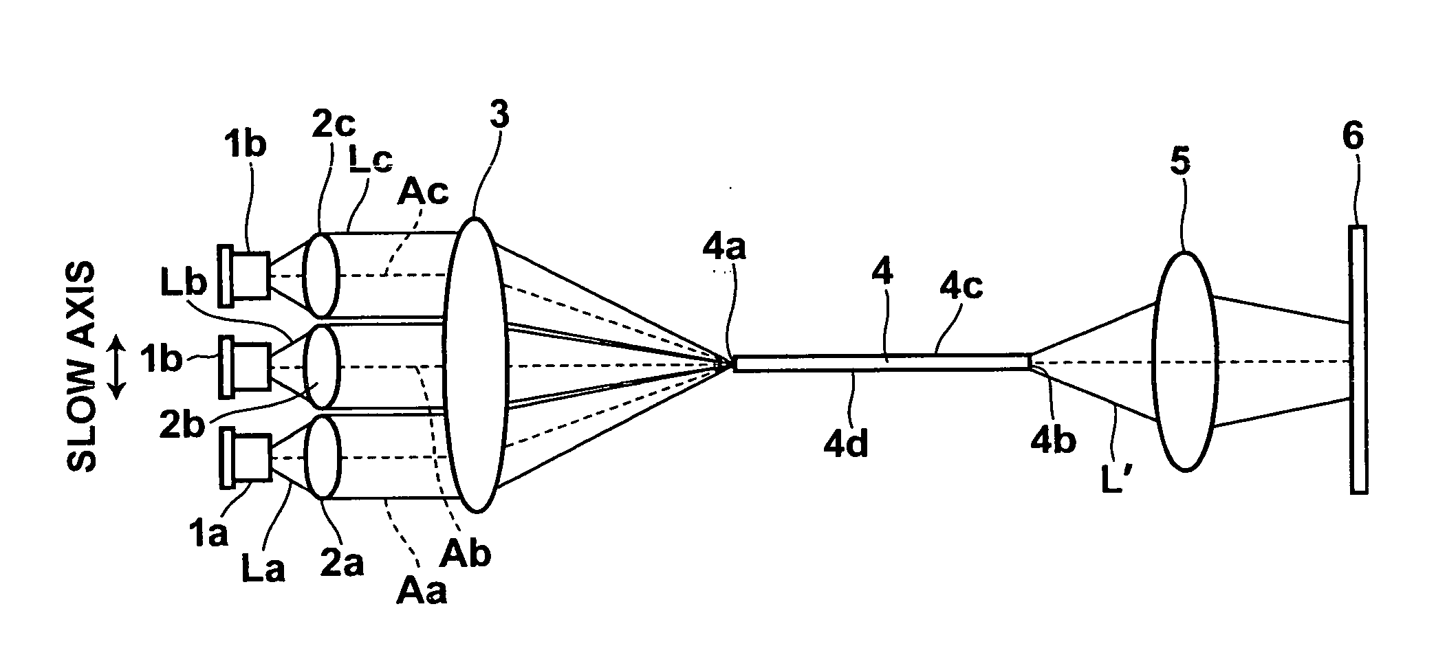
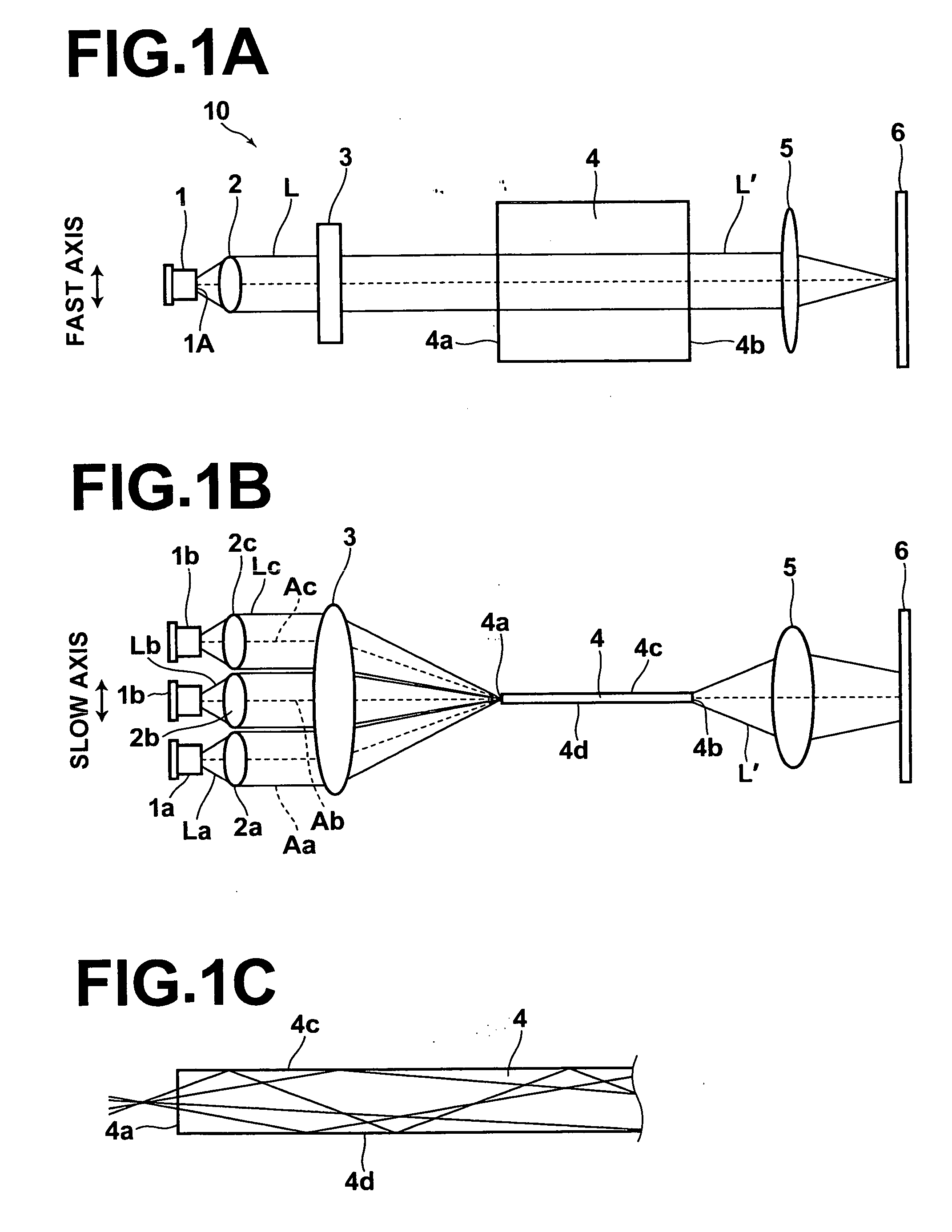
[0035]FIG. 1A is a plan view of a linear light beam generating optical system in accordance with a first embodiment of the present invention as seen from the slow axis, FIG. 1B is a plan view of the linear light beam generating optical system as seen from the fast axis and FIG. 1C is an enlarged view of a part of the plane parallel plate.

[0036] The linear light beam generating optical system 10 of the first embodiment of the present invention comprises a plurality of semiconductor lasers 1 (three in this particular embodiment, and are respectively denoted by 1a, 1b and 1c), a plurality of collimator lenses 2 (three in this particular embodiment, and are respectively denoted by 2a, 2b and 2c) which respectively collimate laser beams L (La, Lb and Lc) emitted from the semiconductor lasers 1a, 1b and 1c, a plane parallel plate 4 which acts as a homogenizer in the direction of the slow axis, a lens 3 which has refractive power only in the direction of the slow axis, and collects the la...


PUM


Abstract

An optical system includes semiconductor lasers arranged in the direction of the slow axis of the laser beam, an optical means which makes parallel the collimated laser beams, an optical member which is provided with inlet and outlet faces which are positioned in perpendicular to the optical axis of laser beams and total reflection surfaces which are opposed to each other at a space where the component in the direction of the slow axis of the laser beam entering from the light inlet face repeats internal reflection, and emits from the light outlet face a slow axis uniform laser beam, and an imaging optical means which images the slow axis uniform laser beam on a surface as a linear line beam extending in the direction of the slow axis.

Description

BACKGROUND OF THE INVENTION [0001] 1. Field of the Invention [0002] This invention relates to a linear light beam generating optical system for generating a linear light beam which is used in a system for rapidly heating or cooling a large area such as a laser annealing system. [0003] 2. Description of the Related Art [0004] There have been known various technologies of linearly projecting a laser beam emitted from a semiconductor laser onto a surface and using the laser beam as a linear light beam. For example, such a linear light beam is used in the field of initialization of an optical disk or laser annealing. [0005] In Japanese Unexamined Patent Publication No. 10(1998)-031820, there is disclosed an optical disk initialization system where a linear light beam projected onto a surface of a medium is used to initialize an optical disk. In the patent publication, there is a disclosure on an optical system which images a light beam emitted from a stripe-like broad area semiconductor...

Claims


Application Information

Patent Timeline
Patent Type & Authority Applications(United States)
IPC IPC(8): G02B27/10
CPCG02B27/0994G02B27/0905
Inventor KATO, KIICHI
Owner FUJIFILM HLDG CORP
Learn More