Testing of spatial light modulators (SLM)

a spatial light modulator and light modulator technology, applied in the field of video display systems, can solve the problems of affecting the quality of the inability to test the image quality of the slm, and the inability to release the improperly operated slm for sale, so as to reduce the overall manufacturing cost of the slm, the effect of less cost and faster performan

Active Publication Date: 2006-11-23
TEXAS INSTR INC
View PDF3 Cites 3 Cited by
  • Summary
  • Abstract
  • Description
  • Claims
  • Application Information

AI Technical Summary

Benefits of technology

[0010] An advantage of a preferred embodiment of the present invention is that the use of stroboscopic techniques can enable the quantitative evaluation of the SLM under test using solely test equipment. Therefore, the tests can be performed faster and at less cost. This can reduce the overall manufacturing cost of the SLM. Furthermore, since test equipment is used in the testing, the test results are reliable and can be readily repeated.
[0011] Yet another advantage of a preferred embodiment of the present invention is the use of s

Problems solved by technology

Even with modern fabrication techniques and facilities, with such a large number of mechanical devices, it is likely that an SLM will have a few faulty light modulators.
It is therefore imperative that SLMs be tested for proper function before they leave the factory so that improperly operating SLMs are not released for sale.
One disadvantage of the prior art that the qualitative evaluation of the image quality of the SLM by a test operator is a slow and potentially error-ridden process.
The use of test operators to determine whether an SLM is

Method used


Image

  • Testing of spatial light modulators (SLM)
  • Testing of spatial light modulators (SLM)
  • Testing of spatial light modulators (SLM)

Examples


Embodiment Construction

[0024] The making and using of the presently preferred embodiments are discussed in detail below. It should be appreciated, however, that the present invention provides many applicable inventive concepts that can be embodied in a wide variety of specific contexts. The specific embodiments discussed are merely illustrative of specific ways to make and use the invention, and do not limit the scope of the invention.

[0025] The present invention will be described with respect to preferred embodiments in a specific context, namely an SLM that makes use of positional micromirrors as light modulators. The invention may also be applied, however, to other SLMs that make use of mirrors as light modulators, such as SLMs using deformable mirrors. Furthermore, the invention can be applied to SLMs using other technologies, such as liquid-crystal display (LCD) and liquid-crystal on CMOS (LCOS) technologies.

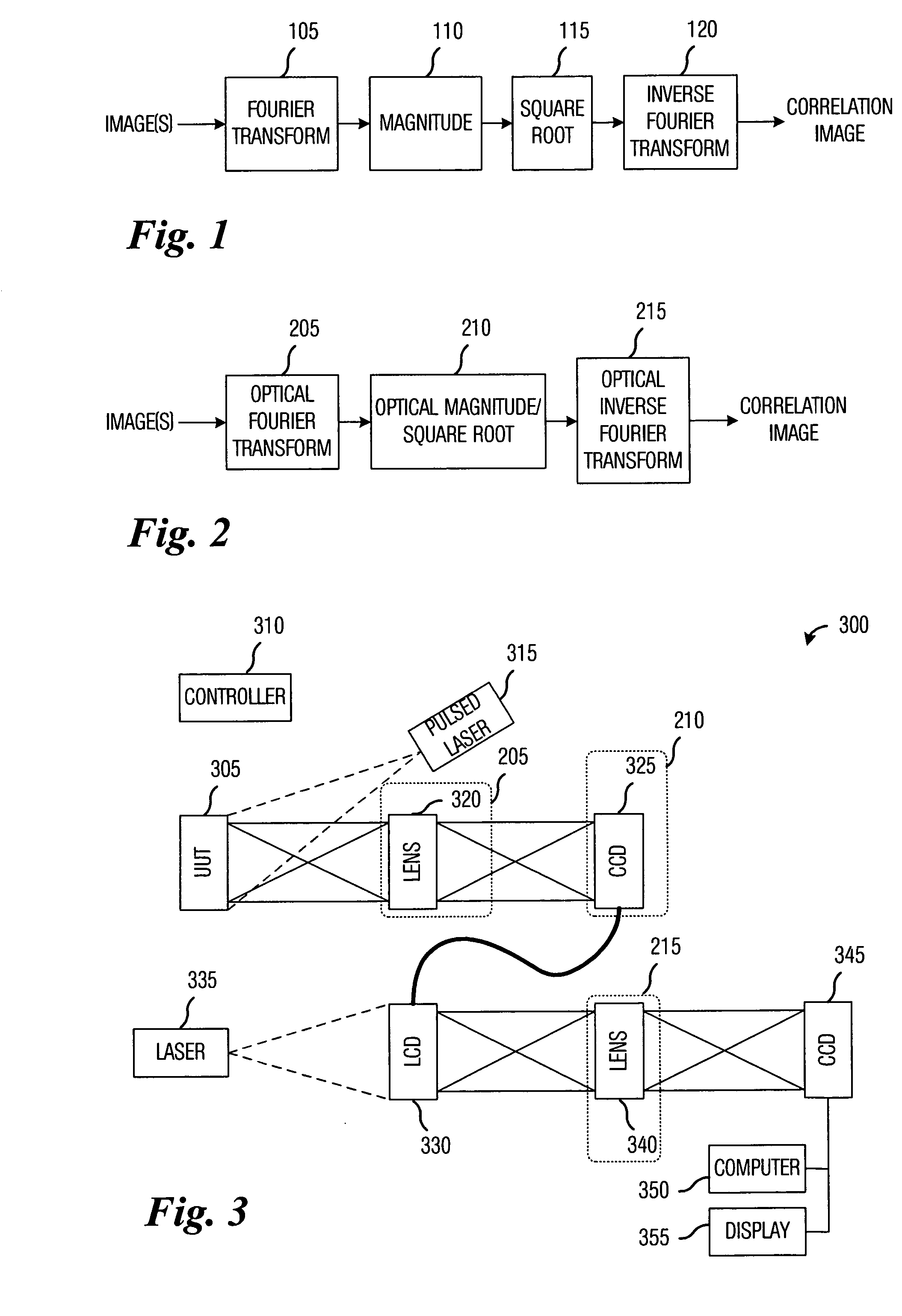
[0026] A cross-correlation image (or simply, correlation image) is an image that illustrate...


PUM


Abstract

System and method for correlation testing of SLMs using stroboscopic methods. A preferred embodiment comprises providing a test pattern to the SLM, configuring a pulsed light source to emit a short duration light pulse at a specified time, instructing the SLM to display the test pattern, emitting the short duration light pulse at the specified time, computing a correlation image based upon light reflected by the SLM, and determining the SLM's performance based upon the correlation image. The pulse of light permits the testing of dynamic and static characteristics of the SLM, while the use of optical computational units in the computation of the correlation image greatly reduces computational requirements and testing time.

Description

TECHNICAL FIELD [0001] The present invention relates generally to a system and method for video display systems, and more particularly to a system and method for correlation testing of SLMs using stroboscopic methods. BACKGROUND [0002] A single SLM, such as a digital micromirror device (DMD) may have up to several million light modulators made from movable (or deformable) mirrors. Even with modern fabrication techniques and facilities, with such a large number of mechanical devices, it is likely that an SLM will have a few faulty light modulators. It is therefore imperative that SLMs be tested for proper function before they leave the factory so that improperly operating SLMs are not released for sale. [0003] One commonly used prior art technique to test SLMs is to place an SLM into a test fixture, configure it to display a series of test images, and have a test operator evaluate the quality of the test images. The test operator can then determine if the SLM is operating properly ba...

Claims


Application Information

Patent Timeline
IPC IPC(8): G02B26/00
CPCG01M11/00G06T7/001G02B26/0833
Inventor REUTER, FRED J.
Owner TEXAS INSTR INC
Why Eureka
Try Eureka