
Heat exchange unit and heat exchanger using the heat exchange unit

a heat exchange unit and heat exchanger technology, applied in indirect heat exchangers, lighting and heating apparatuses, tubular elements, etc., can solve the problems of high manufacturing cost, high manufacturing cost, and difficult processing, and achieve low pressure loss of exhaust, simple structure, and easy manufacturing

Inactive Publication Date: 2006-11-23
JAPAN TIG
View PDF12 Cites 14 Cited by
  • Summary
  • Abstract
  • Description
  • Claims
  • Application Information

AI Technical Summary

Benefits of technology

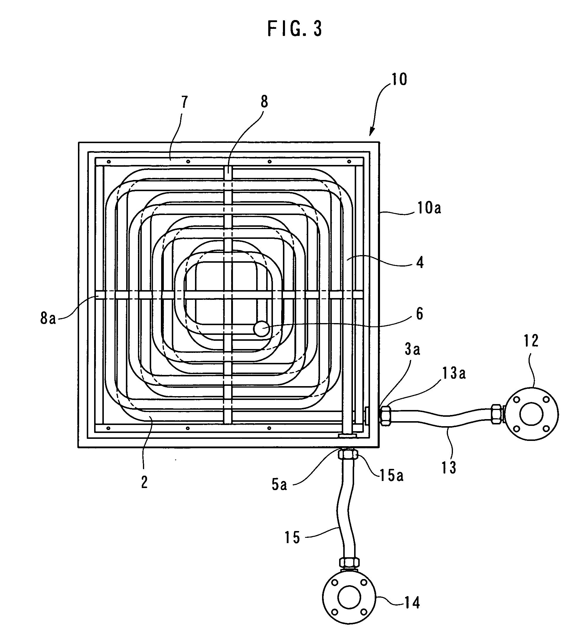
[0019] In the heat exchange unit and the heat exchanger according to the present invention, fluid enters the fluid inlet at, for example, the outer end of the heat exchanger tube of one of the unit elements from the fluid inlet header and flows through the heat exchanger tube toward the center. Then, the fluid enters the heat exchanger tube of the other unit element at the center, flows outward through this heat exchanger tube, and reaches the fluid outlet header. While the fluid flows inward and outward through the coiled heat exchanger tubes, heat, for example, is collected from exhaust which travels through the spaces outside the heat exchanger tubes. The present invention provides the following effects:
[0020] 1. Since the unit elements A and B are combined such that the coiled heat exchanger tubes do not overlap one another, only small portions of the unit elements A and B obstruct the flow of exhaust in a duct. Therefore, pressure loss of the exhaust is low.
[0021] 2. Since the unit elements A and B have simple structures, they can be easily manufactured.
[0022] 3. Since the heat exchanger is simply composed of the unit elements A and B, the heat exchanger has a simple structure and is easily manufactured with low cost.
[0023] 4. The number of units in the heat exchanger disposed in the duct may be increased or reduced. Accordingly, the heat exchanger can be designed and manufactured in accordance with the use thereof.
[0024] 5. When the heat exchanger is structured by combining unit elements A and B formed in conical and inverted conical shapes and is attached to a narrow or thin flue, a required heat transfer area can be ensured.

Problems solved by technology

These known heat exchangers have problems in that they occupy a relatively large space, and that manufacturing costs are high since the heat exchangers must be designed in accordance with the dimensions of the flue and exhaust temperature to ensure efficiency.
In this invention, since a single water tube is bent in the middle into a U-shape and is then coiled, difficult processing is required and manufacturing costs are high.
In addition, when a plurality of coiled water tubes are disposed on one other, efficiency is reduced since the water tubes overlap one another.
Therefore, the flow velocity distribution is not uniform in the flow passage and efficiency is low.
Therefore, the structure is complex and large, and manufacturing costs are high.

Method used


Image

  • Heat exchange unit and heat exchanger using the heat exchange unit
  • Heat exchange unit and heat exchanger using the heat exchange unit
  • Heat exchange unit and heat exchanger using the heat exchange unit

Examples


example 1

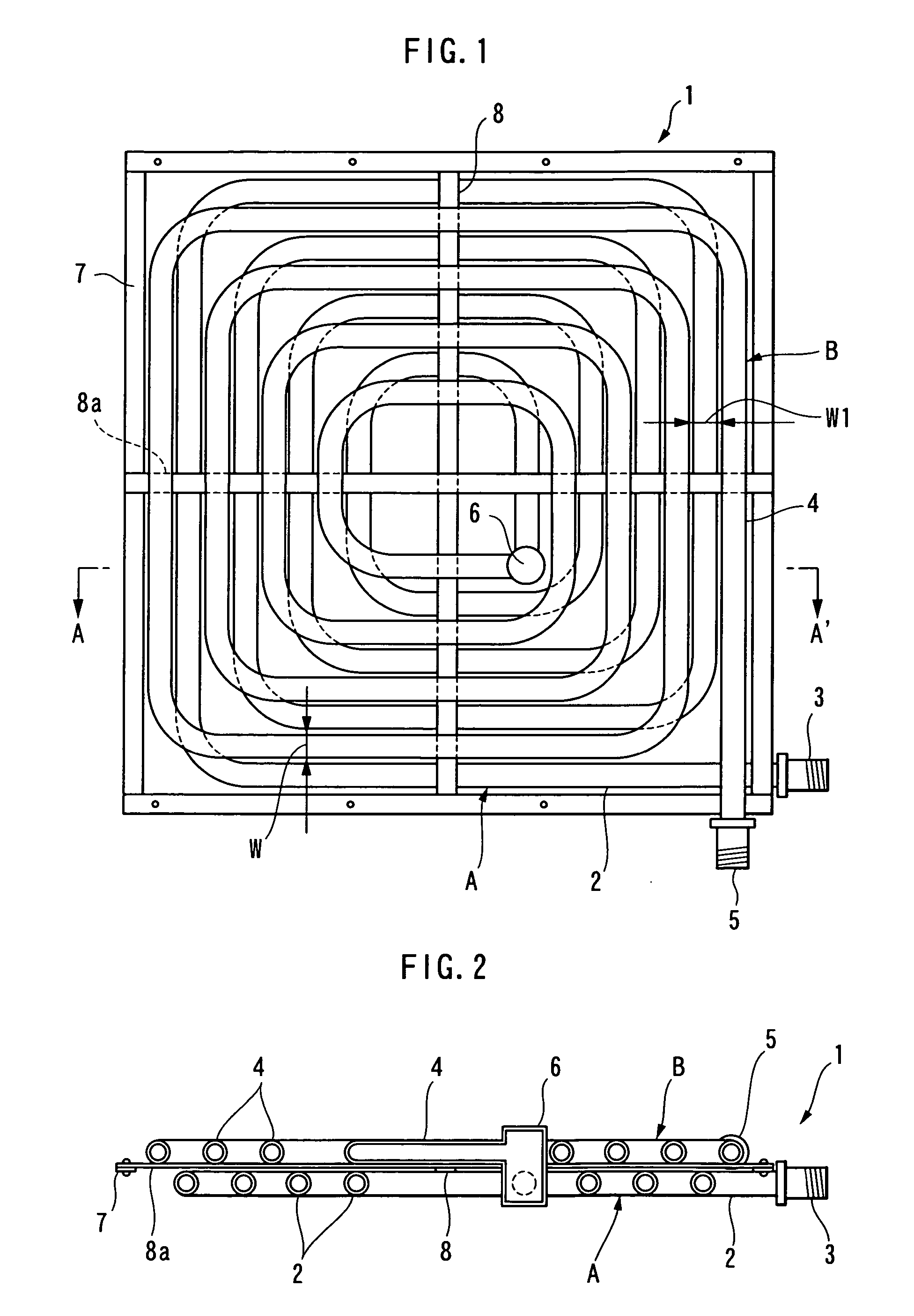
[0055]FIG. 1 is a front view showing a heat exchange unit 1 according to the invention of Claims 1 to 3. FIG. 2 is a sectional view of FIG. 1 taken along line A-A′. FIG. 3 is a front view of a heat exchanger. FIG. 4 is a diagram showing a structure in which the heat exchanger according to the present invention is attached to an exhaust duct to collect latent heat.

[0056] Reference numeral 1 denotes a heat exchange unit. The heat exchange unit 1 includes a unit element A composed of a heat exchanger tube 2 and a unit element B composed of a heat exchanger tube 4. The heat exchanger tube 2 has a fluid inlet 3 at an outer end thereof and is coiled toward the center with predetermined gaps W between successive windings. The heat exchanger tube 4 has a fluid outlet 5 at an outer end thereof and is coiled toward the center with predetermined gaps W1. The heat exchanger tubes 2 and 4 of the unit elements A and B, respectively, are connected to each other with a connection pipe 6 at the inn...

example 2

[0063] In Example 2, a heat exchanger tube 2 is coiled in a single plane. The coiled heat exchanger tube 2 may be used by itself. Alternatively, similar to Example 1, a heat exchange unit 1 may be obtained by combining unit elements A and B together. In FIG. 5, reference numeral 6 denotes a connection pipe which connects heat exchanger tubes 2 of the unit elements A and B to each other at a central position. FIG. 6 shows a heat exchanger 10 obtained by arranging a plurality of heat exchange units 1 having the above structure. In FIG. 6, reference numeral 18 denotes an inlet / outlet header in which a fluid inlet and a fluid outlet are combined. Similar to Example 1, fluid from the header 18 enters, for example, the element A at an outer end of the element A, flows into the element B through the connection pipe 6, and returns to the header 18 from the element B at the outer end of the element B.

[0064] Also in Example 2, the heat exchanger 10 may be designed to have a desired number of...

example 3

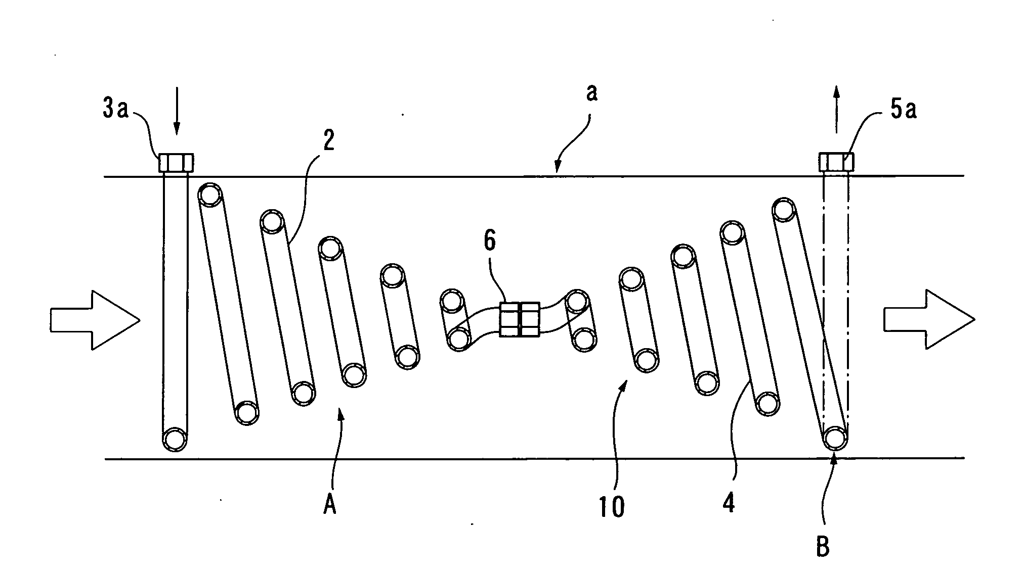
[0065] Example 3 corresponds to the invention of Claim 4. As shown in FIG. 7, Example 3 differs from Examples 1 and 2 in that heat exchanger tubes 2 and 4 are helically coiled into a conical shape and an inverted conical shape, respectively, instead of being coiled in a single plane. An element A and an element B having the conical and inverted conical shapes are connected to each other with a connection pipe 6 to form a heat exchange unit 1. The heat exchange unit 1 is installed in, for example, a flue a.

[0066] When a plurality of heat exchange units 1 having the above structure are combined, the heat exchange units 1 may be arranged along the longitudinal direction thereof Such a structure is advantageous in increasing a heat transfer area while keeping pressure loss in the flue a as low as possible when the diameter of the flue a is small. In addition, pressure loss of fluid which flows through the heat exchanger tubes 2 and 4 is also reduced and the performance is effectively i...


PUM


Abstract

A heat exchange unit and a heat exchanger having simple structures which can be manufactured at low cost are provided. The capacity and efficiency of the heat exchanger can be set in accordance with conditions. Heat exchanger tubes 2 and 4 are coiled with predetermined gaps to form heat exchange unit elements A and B, respectively. The elements A and B are shifted from each other so that the tubes 2 and 4 do not overlap each other. The elements A and B are connected to each other with a connection pipe 6 at inner ends thereof Fluid enters the element A from an inlet header 12, flows into the element B through the connection pipe 6 at the center of element A, and then flows out of the element B through an outlet header 14. Heat is collected during this time.

Description

FIELD OF THE INVENTION [0001] The present invention relates to a heat exchange unit for collecting latent or sensible heat and a heat exchanger using the heat exchange unit. BACKGROUND OF THE INVENTION [0002] In general, known heat exchangers for collecting latent or sensible heat include a heat exchanger tube provided with fins and installed in a snaking fashion, or multiple heat exchanger tubes disposed so as to extend through a flue or the like. These known heat exchangers have problems in that they occupy a relatively large space, and that manufacturing costs are high since the heat exchangers must be designed in accordance with the dimensions of the flue and exhaust temperature to ensure efficiency. In order to solve these problems, Japanese Unexamined Patent Application Publication No. H9(1997)-72679 discloses a heat exchanger including a coiled heat exchanger tube. [0003] According to this published invention, in order to reduce the capacity of a boiler or the like, a water t...

Claims


Application Information

Patent Timeline
Patent Type & Authority Applications(United States)
IPC IPC(8): F28F9/22
CPCF28D7/028F28F9/26F28F1/08
Inventor NAKAGAWA, YASUAKIINAGAKI, KATSUYUKIOZAWA, RYUJI
Owner JAPAN TIG
Learn More