
Hybrid drive unit, and method of controlling a gear shift sequence in a manual shift transmission of a hybrid drive unit

a hybrid drive and gear shift technology, applied in the direction of mechanical equipment, propulsion parts, transportation and packaging, etc., can solve the problems of increasing the manufacturing cost and the space required for such a hybrid drive uni

Inactive Publication Date: 2006-11-16
GM GLOBAL TECH OPERATIONS LLC
View PDF3 Cites 16 Cited by
  • Summary
  • Abstract
  • Description
  • Claims
  • Application Information

AI Technical Summary

Benefits of technology

[0008] An object of the present invention is to propose a hybrid drive unit of the aforementioned type, which for propelling a hybrid drive vehicle forwards allows substantially smooth manual gear shift both for individual operation of an internal combustion engine or an electric motor, as well as for a combined hybrid operation of the internal combustion engine and of the electric motor, with the aid of a single clutch.
[0009] To achieve this object the hybrid drive unit according to the invention is characterized by the features specified in the independent claim 1 below. By controlling the electric motor by means of an electronic control unit, when manually shifting the gear in all operating modes, so that the electric motor, to a sufficient extent, brakes or accelerates the second input shaft of the transmission to a rotational speed suited to a higher or lower gear, respectively, the input shaft can be made to instantaneously become essentially torque-free just prior to active engagement of the relevant gear of the transmission. In all operating modes this allows an essentially smooth gear shift sequence to be achieved without the need for a separate clutch between the electric motor and the transmission.

Problems solved by technology

In addition to this clutch, the clutch normally situated between the internal combustion engine and the transmission is also required, that is to say in all two separate clutches, which means an increase in the manufacturing cost and the space required for such a hybrid drive unit.

Method used


Image

  • Hybrid drive unit, and method of controlling a gear shift sequence in a manual shift transmission of a hybrid drive unit
  • Hybrid drive unit, and method of controlling a gear shift sequence in a manual shift transmission of a hybrid drive unit

Examples


Embodiment Construction

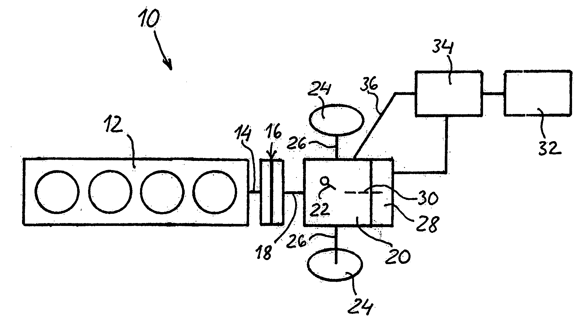
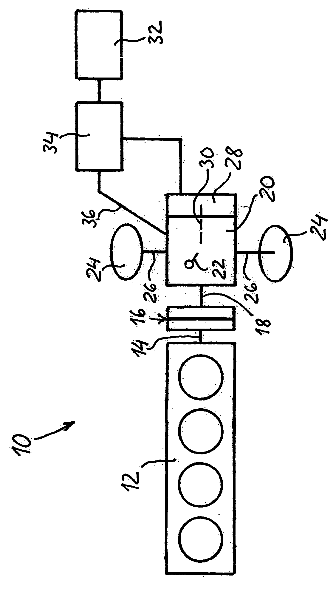
[0015] In the drawing a hybrid drive unit according to the present invention is generally denoted by 10. In its basic construction the hybrid drive unit 10 comprises an internal combustion engine 12 of any type known in the art. The crankshaft (not shown) of the engine 12 is coupled by way of an output shaft 14 to a manually operated clutch 16 that can be engaged and disengaged, which may be of any suitable known type, such as an electromagnetic, hydraulic or friction clutch. The clutch 16 is furthermore connected to a first input shaft 18 of a multi-step gearbox or transmission 20, which can be manually operated by means of an operating device 22, for example a gear lever, steering wheel paddles, or the like. A pair of driving wheels 24 of the vehicle are each connected to the transmission 20 by way of a respective drive shaft 26. An electric motor 28, which is preferably of a compact disk-shaped type and is integrated with the transmission 20, is likewise connected to the transmis...


PUM


Abstract

A hybrid drive unit comprising an internal combustion engine; a manual transmission; a manual clutch that can be engaged and disengaged, connected to the internal combustion engine and to a first input shaft of the transmission; at least one electric motor, connected to a second input shaft of the transmission and driveable from a chargeable electrical voltage source; and an electronic control unit connected to the electric motor. When manually upshifting and downshifting the transmission the electronic control unit is designed, without the use of a clutch between the electric motor and the transmission, to instantaneously make the second input shaft essentially torque-free by controlling the electric motor to brake and accelerate the second input shaft to a rotational speed suited to a higher and a lower, respectively, gear prior to active engagement of the relevant gear.

Description

REFERENCE TO RELATED APPLICATION [0001] This application claim the benefit of the filing dated of Swedish Patent Application No: 0500445-2, filed Feb. 28, 2005, the disclosure of which is hereby incorporated by reference. BACKGROUND OF THE INVENTION [0002] 1. Technical Field [0003] The present invention relates to a hybrid drive unit, which comprises a prime mover in the form of an internal combustion engine having an output shaft coupled to a crankshaft of the engine; a transmission manually operated by a gear shift device; a manual clutch that can be engaged and disengaged, connected to the output shaft from the internal combustion engine, and to a first input shaft of the transmission; at least one secondary drive motor in the form of an electric motor, connected to a second input shaft of the transmission and driveable from a chargeable electrical voltage source; and an electronic control unit connected to the electric motor, the hybrid drive unit having three selectable operati...

Claims


Application Information

Patent Timeline
IPC IPC(8): B60L8/00B60K6/48B60W10/10B60W30/18
CPCB60K6/48B60W10/08B60W10/11Y02T10/6221B60W30/19F16H61/0403F16H2061/0422B60W20/00Y02T10/62Y02T10/7072B60K17/02B60W20/40
Inventor ANDERSSON, ROLANDALAKULA, MATS
Owner GM GLOBAL TECH OPERATIONS LLC
Learn More