
Systems and methods for acquiring data in thermal recovery oil wells

a technology for thermal recovery oil wells and data acquisition systems, applied in the direction of reradiation detection, nuclear radiation detection, electric/magnetic detection for well-logging, etc., can solve the problems of long lengths of wires or cables, data transmitted across these relatively long spans of wiring or cables can degrade, weaken, and be corrupted by noise, etc., to achieve the effect of reducing the cost of such wiring, and reducing the cos

Active Publication Date: 2006-11-09
CORE LAB CANADA
View PDF5 Cites 60 Cited by
  • Summary
  • Abstract
  • Description
  • Claims
  • Application Information

AI Technical Summary

Benefits of technology

[0015] It should be understood that examples of the more important features of the invention have been summarized rather broadly in order that detailed description thereof that follows may be better understood, and in

Problems solved by technology

There exists throughout the world major deposits of heavy oils which, until recently, have been substantially ignored as sources of petroleum since the oils contained therein were not recoverable using ordinary production techniques.
As can be appreciated, the costs of such wiring can become considerable because the length traversed by the wires can approach several kilometers.
Furthermore, the data transmitted across these relatively long spans of wiring or cables can degrade and weaken and be corrupted by noise.
The long lengths are also prone to accuracy loss caused by wire impurities, insulation breakdown, and low voltage signal degradation.
Likewise, fiber optic cables sensors as well as the associated fiber optic cables are relatively expensive and prone to degradation in signal accuracy and strength due to hydrogen related problems with the glass fiber.
Moreover, in both instances, the splices or couplings between individual lengths of cable can introduce noise and errors into the transmitted data.
Yet another difficulty and expense arises from the need to effectively seal and pack-off multiple wires or multiple bundles of cables exiting the wellhead.

Method used


Image

  • Systems and methods for acquiring data in thermal recovery oil wells
  • Systems and methods for acquiring data in thermal recovery oil wells
  • Systems and methods for acquiring data in thermal recovery oil wells

Examples


Embodiment Construction

[0031] The present invention relates to devices and methods for acquiring and transmitting signals / data from a wellbore to a surface location. The present invention is susceptible to embodiments of different forms. There are shown in the drawings, and herein will be described in detail, specific embodiments of the present invention with the understanding that the present disclosure is to be considered an exemplification of the principles of the invention, and is not intended to limit the invention to that illustrated and described herein.

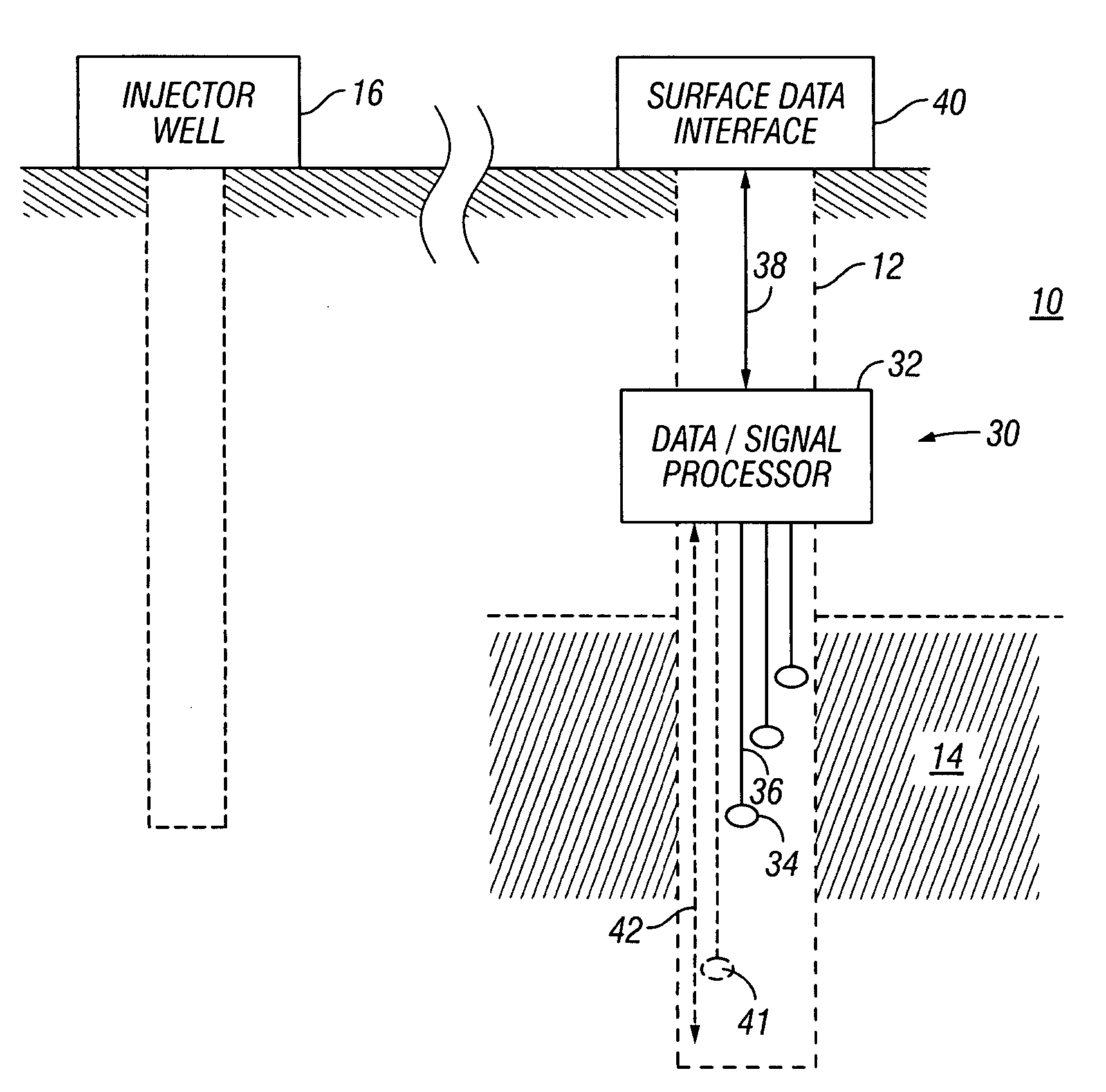
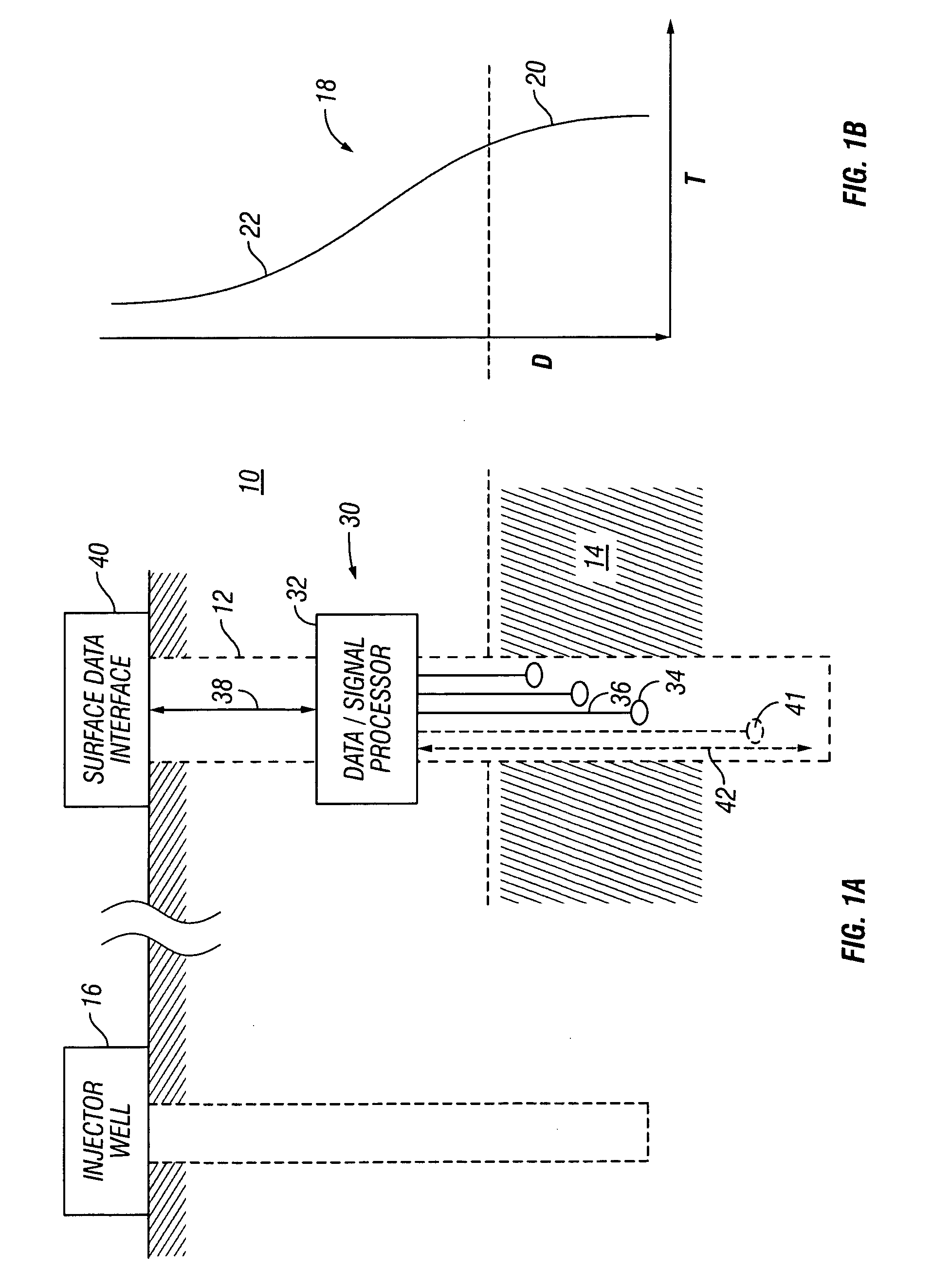
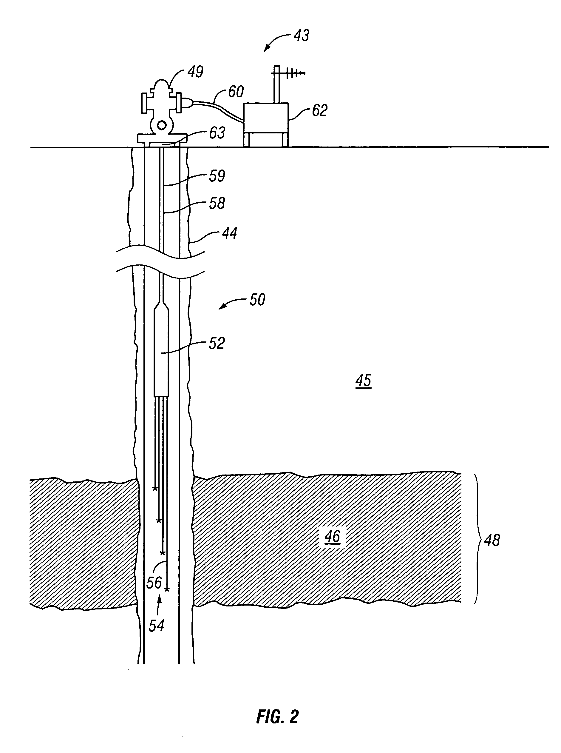
[0032] Referring initially to FIG. 1A, there is schematically an arrangement for recovering hydrocarbons such as oil, heavy oil, or bitumen, from a subterranean formation 10. A wellbore 12 drilled into the formation 10 intersects a hydrocarbon reservoir or pay zone 14. The wellbore 12 can include known equipment such as a cemented casing. While one reservoir 14 is shown, it should be understood that the wellbore 12 can intersect multiple pay zones....


PUM


Abstract

In connection with thermal recovery projects, a system determines temperature gradients for a heat affected zone associated with a subterranean hydrocarbon reservoir. An exemplary system includes a plurality of temperature sensors distributed in the wellbore at least partially along the heat affected zone. A downhole processor positioned proximate and substantially outside of the heat affected zone receives and digitizes the temperature measurements. A data link such as a data cable coupled to the downhole processor conveys the temperature measurements to a surface interface.

Description

CROSS-REFERENCE TO RELATED APPLICATIONS [0001] This application Claims the benefit of earlier filed provisional U.S. Patent Application Ser. No. 60 / 672,404, filed on Apr. 18, 2005.BACKGROUND OF THE INVENTION [0002] 1. Field of the Invention [0003] The present invention relates to data acquisition systems and methods for oil and gas wells. In one aspect, the present invention relates to systems and methodologies for determining temperature gradients in connection with thermal recovery projects involving oil or gas wells. [0004] 2. Description of the Related Art [0005] There exists throughout the world major deposits of heavy oils which, until recently, have been substantially ignored as sources of petroleum since the oils contained therein were not recoverable using ordinary production techniques. These oil deposits are also referred to as heavy oil, or bitumen. For example, it was not until the 1980's that much interest was shown in the heavy oil deposits of the Alberta province in ...

Claims


Application Information

Patent Timeline
IPC IPC(8): G01V3/00E21B47/01E21B47/00E21B47/07E21B47/12
CPCG01V11/002E21B47/065E21B47/07
Inventor MOMBOURQUETTE, IVANJABUSCH, KIRBYBUSSIERE, COLIN
Owner CORE LAB CANADA
Learn More