Cast-in anchors

a technology of anchors and cast-ins, which is applied in the direction of nails, mechanical equipment, fastening means, etc., can solve the problems of increasing material costs, affecting the installation of anchors prior to casting, and failure mode of this type of anchors, and achieves the effect of significantly more rapid achievemen

Active Publication Date: 2006-11-09
ILLINOIS TOOL WORKS INC
View PDF24 Cites 21 Cited by
  • Summary
  • Abstract
  • Description
  • Claims
  • Application Information

AI Technical Summary

Benefits of technology

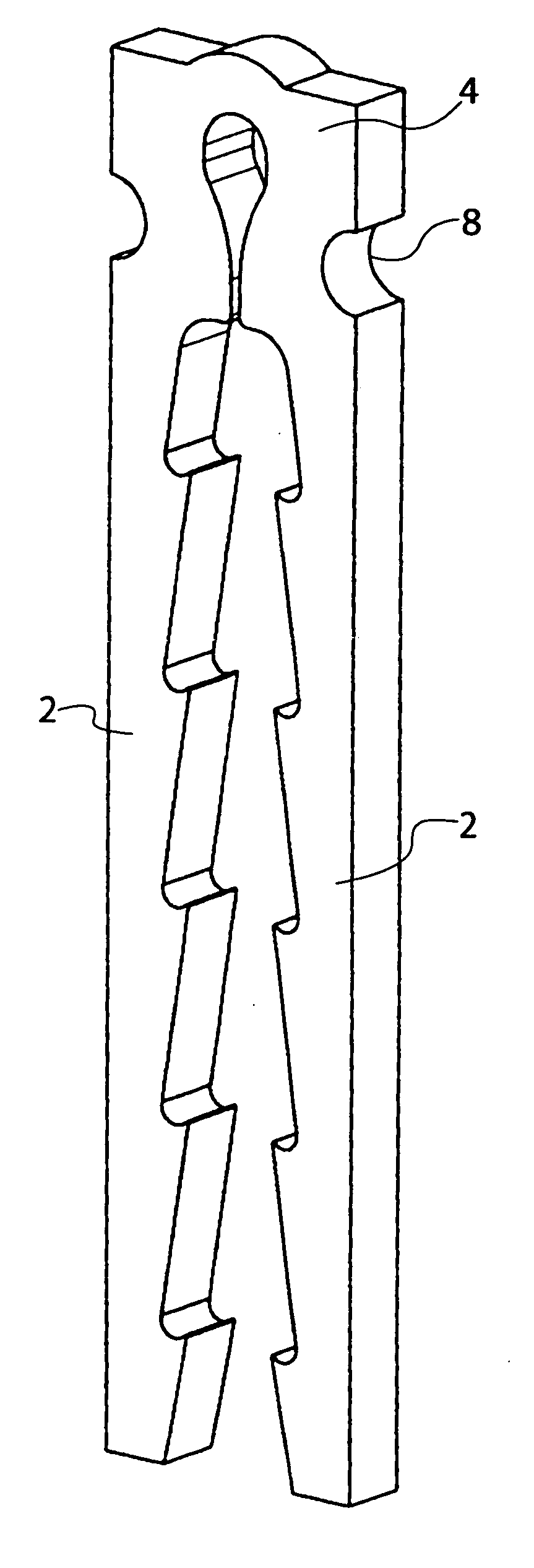
[0011] In a preferred embodiment, the effect is achieved by profiling the inner edge of the leg with a series of longitudinally spaced formations which lock into the concrete, each of the formations inclining upwardly and inwardly so as to face towards the head. With this arrangement the leg tends to lock tighter into the concrete as the load increases.
[0012] With this configuration, the outer edge of the leg can be kept straight and this is of particular advantage when the anchor is being cut out of thick metal plate by laser beam or plasma arc as cutting in a straight line is able to be accomplished significantly more quickly than when cutting along a complex path. It is however within the scope of the invention for the outer edge of the leg also to be suitably profiled.
[0014] When using an anchor as described above, it is envisaged that a tension bar to increase the load capacity of the anchor can be installed between the two legs adjacent to the underside of the head but without actually physically contacting the head as there will be load transmission between the tension bar and the head via the intervening concrete.
[0026] Although these methods providing a threaded fixing point have significant utility in a plate anchor formed with integral anchoring legs designed in accordance with the principles discussed above, they also have utility in more conventional forms of plate anchors such as those with anchoring formations formed by lengths of reinforcing bar bent into U shape and welded to the rear of the plate.

Problems solved by technology

However a potential failure mode with this type of anchor arises if the strength of the concrete to the outside of the leg is insufficient to withstand the forces acting on the leg from its inner face and acting in a sense to force the leg outwardly.
With existing anchors of this type, the need to produce the anchor with relatively long legs increases the material costs and also can sometimes complicate the installation of the anchor prior to casting.

Method used


Image

  • Cast-in anchors
  • Cast-in anchors
  • Cast-in anchors

Examples


Embodiment Construction

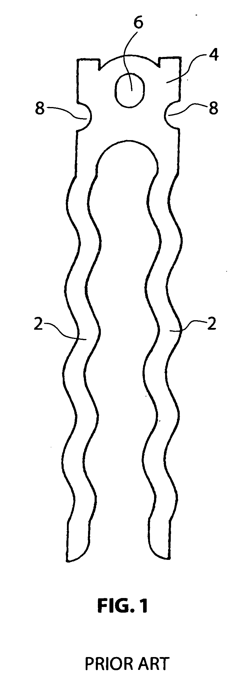
[0039] The anchor shown in FIGS. 2 and 3 is of the general type shown in FIG. 1 with a head 4 for coupling to lifting apparatus and a pair of substantially parallel legs 2 extending from the head 4. The particular head 4 shown is designed for co-operation with a lifting clutch in the form of a ring clutch with an arcuate locking bolt received within the eye 6 although it is to be understood that the head 4 could be of a different detailed design for use with other types of lifting apparatus. As with the prior anchor, the anchor is cut from thick metal plate by laser beam or plasma arc cutting. In the particular form shown, the eye 6 is also laser or plasma cut as part of a continuous cutting operation as described in our patent 751863. However the eye could alternatively be formed by a separate stamping operation after cutting the anchor.

[0040] In the conventional wave profile in the anchor in FIG. 1, the profile at the inner edge of the leg engenders, when the anchor is under load...


PUM


Abstract

An anchor for embedment into a concrete component, has a head via which load is applied to the anchor in use and an anchoring formation provided by at least one leg extending from the head and profiled along an edge thereof so as to lock into the surrounding concrete. The profile is formed by a series of longitudinally spaced formations each of generally saw-toothed shape with a leading edge of each formation inclining towards the head such that on application of a pulling load to the head the leg will lock tighter into the concrete with increasing load. In one form the anchor is a lifting anchor and having a pair of such legs extending from the head which is adapted for releasable engagement with lifting equipment, and the profile is formed along an inner edge of each of the legs. In an alternative form the anchor is a plate anchor in which the head of the anchor is formed by a plate and a set of such legs extends from each of two opposite sides of the plate transversely to the plane of the plate. Each set of legs comprises at least two parallel legs and the profile is formed along an inner edge of each of said legs.

Description

BACKGROUND OF THE INVENTION [0001] 1) Field of the Invention [0002] The present invention relates to anchors intended to be incorporated into a concrete component prior to casting, for example lifting anchors to provide a lifting point by which the component can be lifted during subsequent erection, and anchors for providing a fixing point for other components post-erection. [0003] 2) Description of the Prior Art [0004] Concrete lifting systems for lifting of concrete panels, beams and other components typically involve the use of lifting anchors incorporated into the component during casting, with the head of the anchor being encased within a removable or disposable hollow void former to form within the surface of the component a recess within which the head of the anchor lies for releasable coupling to lifting equipment. [0005] Different types of lifting anchor are required for different components, loads, and type of lift. FIG. 1 shows an anchor which has been widely used for edg...

Claims


Application Information

Patent Timeline
IPC IPC(8): E04G21/14E02D35/00
CPCE04G21/142
Inventor FLETCHER, GOEFFCONNELL, ROBERT URQUHART
Owner ILLINOIS TOOL WORKS INC
Why Eureka
Try Eureka