
Compressive orthosis for the lower limb in the form of a knitted article of the stocking, sock, or tights type

Active Publication Date: 2006-11-02
INNOTHERA TOPIC INT
View PDF7 Cites 51 Cited by
  • Summary
  • Abstract
  • Description
  • Claims
  • Application Information

AI Technical Summary

Benefits of technology

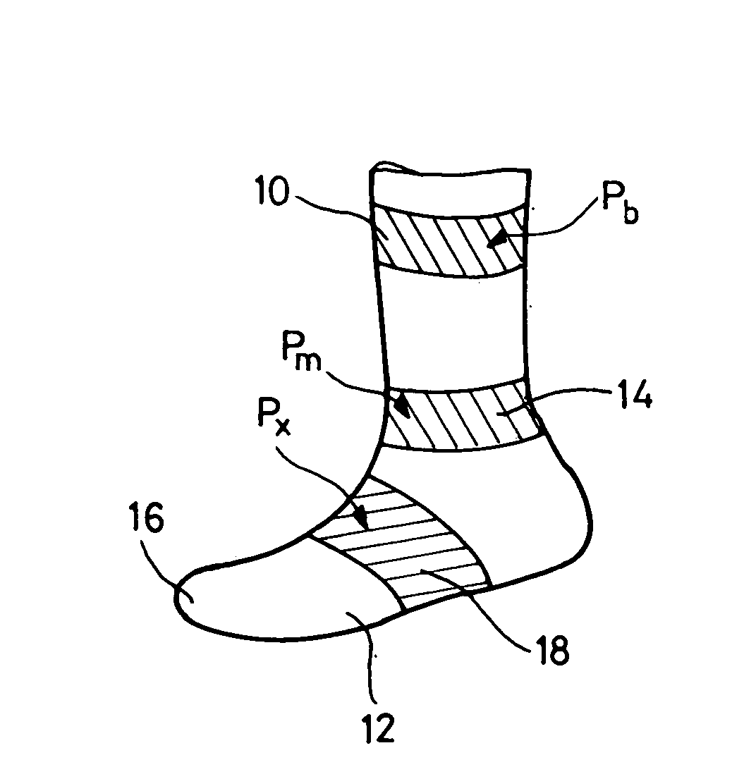
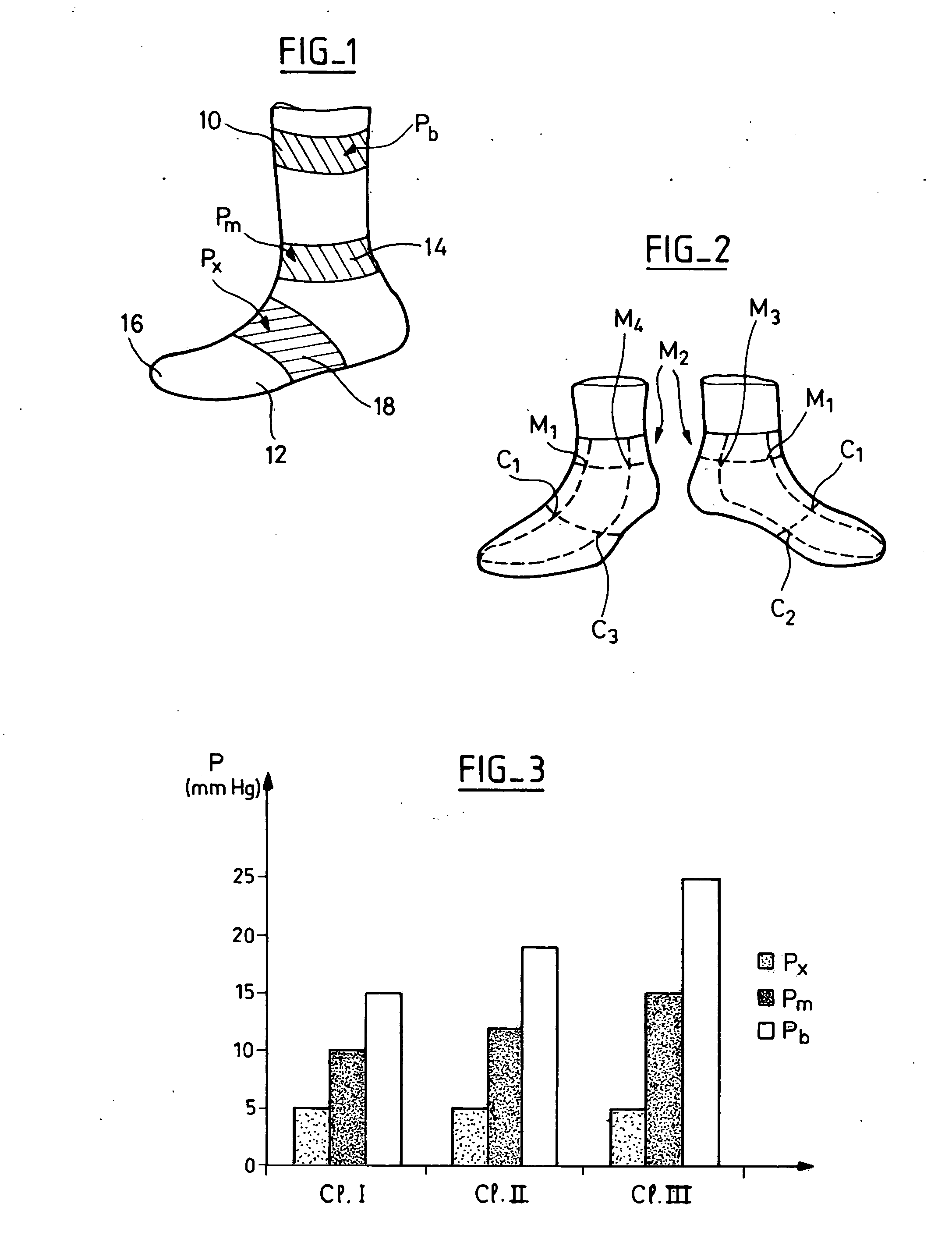
[0020] More precisely, the invention provides a medical elastic orthosis presenting a pressure profile in which the pressure delivered to the instep is reduced to a value close to that obtained with a non-medical fabric. In the malleolar region, pressure is delivered at a value lying between that delivered to the instep and the value prescribed for the ankle as a function of the selected class of compression. In this way, the orthosis presents a progressive pressure profile between the foot and the ankle, thereby making it possible to avoid a tourniquet effect at the ankle.

Problems solved by technology

This phenomenon is due to the very tight texture of the elastic stocking, which is needed in order to produce a medical effect on the leg, but which leads to residual compression on the foot, in particular in the malleolar and instep regions, where said residual compression produces excess pressure leading to the above-mentioned drawbacks.
the anatomy of the arch of the foot lends itself poorly to compression, and any veins that might need compressing (in the sole) are under the arch.
The only vulnerable position is the sitting position associated with total inactivity of the foot and of the ankle.
with some subjects, the arterial vascularization of the front of the foot is vulnerable specifically as a result of anatomy.
in other patients, problems arise because of deformations of the metatarsus (hallux valgus, overlapping little toe, sag foot), still by the combination of “Laplace's equation+compression becoming excessive on a surface having a small radius of curvature”;
. . ), the iatrogenic risk of excess pressure on the instep and the back of the foot becomes highly perceptible.
In addition, pressure at the foot is not controlled and consequently pressure at the instep can be even greater than the pressure exerted at the ankle.

Method used


Image

  • Compressive orthosis for the lower limb in the form of a knitted article of the stocking, sock, or tights type
  • Compressive orthosis for the lower limb in the form of a knitted article of the stocking, sock, or tights type

Examples


Embodiment Construction

[0029]FIG. 1 shows the various regions of the bottom portion of the orthosis, which is an orthosis that is closed in its bottom portion, i.e. it completely envelops the foot, e.g. like a sock, a stocking, or tights.

[0030] These various regions comprise a leg portion 10 extending upwards from the ankle (and including the ankle region), a foot portion 12 extending from the malleolar region 14 (and including the malleolar region) as far as the toe region 16, and covering the intermediate region 18 of the instep.

[0031] The leg portion 10 is a compressive tubular portion, itself conventional and unmodified, having a mesh structure and dimensioning that are selected so as to apply therapeutic compression to the leg once the orthosis has been put on said limb.

[0032] The stitch used may be of the same type as those used in conventional elastic stockings, for example of the weft, plain, pinched or float micromesh, etc. type, all stitches that are themselves known to specialists in knittin...


PUM


Abstract

The orthosis comprises a leg portion and a foot portion. The leg portion which extends upwards from the ankle serves to apply therapeutic compression to the leg once the orthosis has been put on. The foot portion which extends from the malleolar region to the toes and covers the instep is a shaped portion that envelops the foot elastically. The dimensioning and the mesh structure of the foot portion are such that 0<Px<Pm<Pb once the orthosis has been put on, Px being the pressure applied to the instep region, Pm being the pressure applied to the malleolar region, and Pb being the therapeutic compression applied to the ankle region. Preferably, Px=5 mmHg±25% and Pm=0.5(Pb+Px)±25%.

Description

FIELD OF THE INVENTION [0001] The invention relates to orthoses generally known as “elastic stockings” or “elastic tights”. [0002] Although the term “stocking” is used below, the invention is not limited to one particular type of article, and it applies equally well to all forms of compressive orthoses for one or both lower limbs, whether in the form of tights, single-leg tights, stockings, or socks. [0003] The invention relates more specifically to “elastic stockings” that are medical stockings producing a therapeutic effect by compressing / restraining the lower limbs, in opposition to “support stockings” (or “anti-tiredness stockings”) and to “fashion stockings” which are not medical stockings having a therapeutic purpose. BACKGROUND OF THE INVENTION [0004] Medical elastic stockings are stockings which exert pressure as measured at the ankle lying in the range 10 millimeters of mercury (mmHg) to more than 36 mmHg (equivalent to 13 hecto pascals (hPa) to 48 hPa, but the present desc...

Claims


Application Information

Patent Timeline
IPC IPC(8): A61F13/06
CPCA61F13/08A41B11/003A61F5/0111
Inventor GOBET, ARNAUDCROS, FRANCOIS
Owner INNOTHERA TOPIC INT
Learn More