Transparency-conserving method to generate and blend images

Active Publication Date: 2006-11-02
NVIDIA CORP
View PDF26 Cites 10 Cited by
  • Summary
  • Abstract
  • Description
  • Claims
  • Application Information

AI Technical Summary

Benefits of technology

[0025] A system embodying the invention includes a controlling device and a set of rendering devices, with the effect that the controlling device can distribute a set of objects to the rendering devices. Each rendering device computes a (2D) image in response to the objects assigned to it, including computing multiple overlapping images and using a graphics processor to blend those images into a resultant image. To interface with the graphics processor, each rendering device spoofs the α-value with a pixel feature other than opacity (opacity is expected by the graphics processor), with the effect that the graphics processor delivers useful α-values, while still delivering correct color values, for each pixel. This has the effect that the resultant images include transparency information sufficient to combine them using transparency blending instead of alpha blending. Since the transparency is defined by 1—opacity, this operation leads mathematically to the same results, but allows the usage of graphics hardware and existing software standards like OpenGL.

Problems solved by technology

A first problem in the known art is how to blend transparent (or partially transparent) components, such as for example a view of a window, a tinted window, or a translucent plastic object.
This problem can occur in different computer-graphics applications.
A drawback of the known solutions is that the opacity-values of images rendered by graphics hardware do not reflect the accumulated opacity per pixel at the end of the rendering process.
A second problem in the known art is that computing an image to be presented (whether from a 2D image description, or from a 3D scene description) requires relatively large resources, including both computing power and memory.
This possibility is subject to the drawback that a general-purpose processor would be substantially slower than graphics hardware.

Method used


Image

  • Transparency-conserving method to generate and blend images
  • Transparency-conserving method to generate and blend images
  • Transparency-conserving method to generate and blend images

Examples


Embodiment Construction

[0040] The description includes a preferred embodiment of the invention, including preferred process steps and data structures. Those skilled in the art would realize, after perusal of this application, that embodiments of the invention might be implemented using a variety of other techniques not specifically described, without undue experimentation or further invention, and that such other techniques would be within the scope and spirit of the invention.

DEFINITIONS

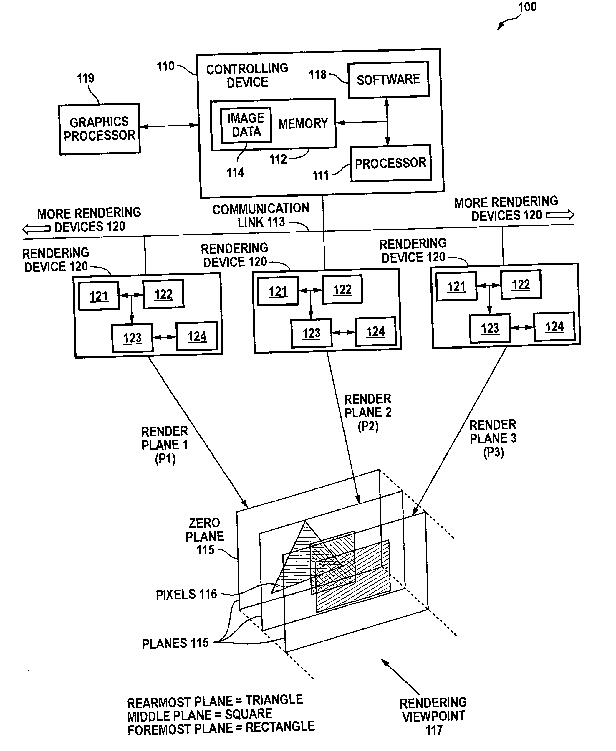
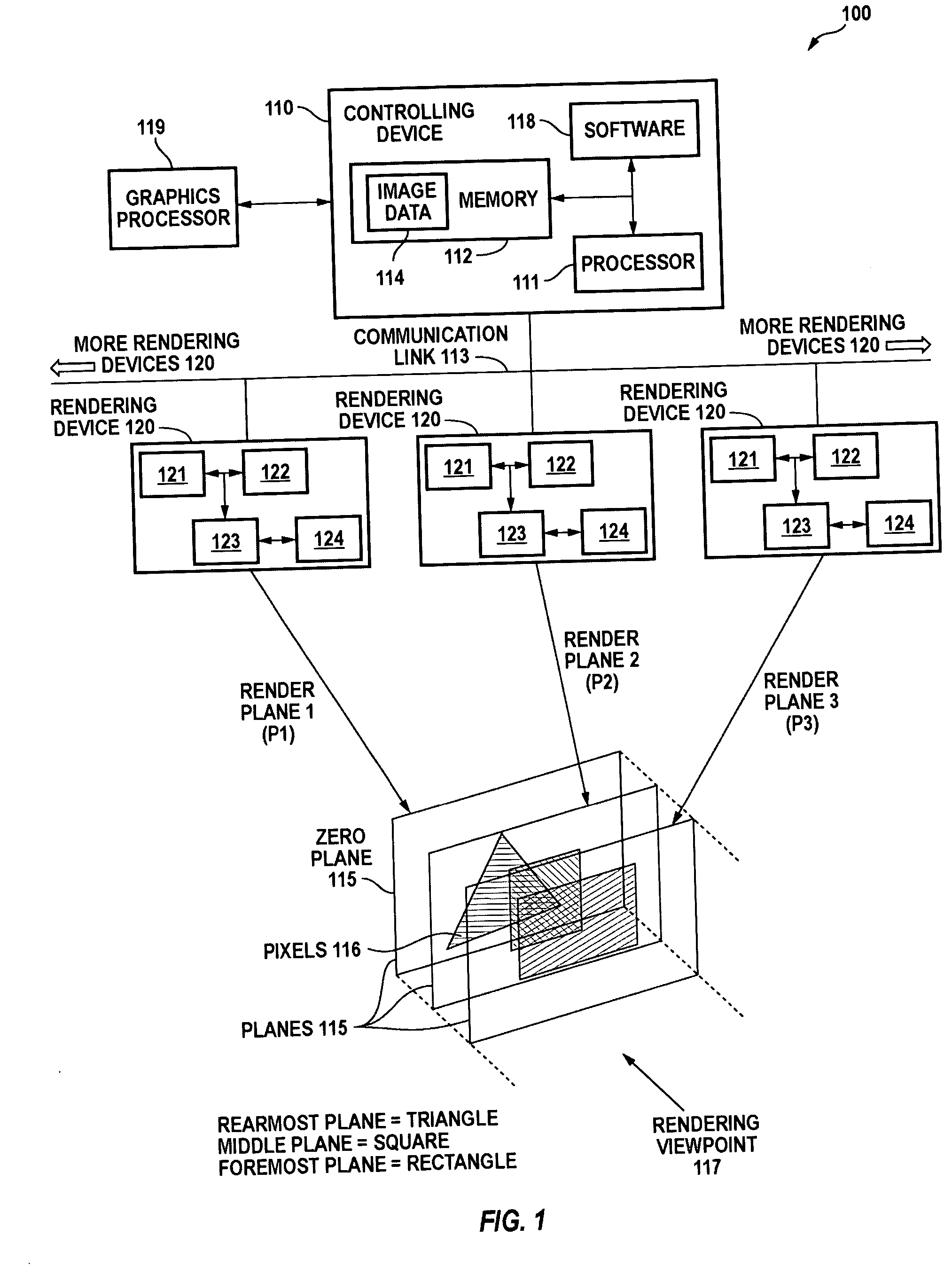
[0041] The general meaning of each of these following terms is intended to be illustrative and in no way limiting. [0042] The phrases (1) “controlling device” and (2) “rendering device”, and the like, refer respectively to devices for (1) controlling the allocation of rendering commands, and (2) actually rendering 3D scenes and 2D images of those 3D scenes from a selected perspective, as further described below. [0043] In one embodiment, there is a single controlling device and as many rendering devices as necessary so ...


PUM


Abstract

A system embodying the invention includes a controlling device 110 and a set of rendering devices 120, with the effect that the controlling device 110 can distribute a set of objects to the rendering devices 120. Each rendering device 120 computes a (2D) image in response to the objects assigned to it, including computing multiple overlapping images and using a graphics processor 119 to blend those images into a resultant image. To interface with the graphics processor, each rendering device 120 spoofs the α-value with a pixel feature other than opacity (opacity is expected by the graphics processor 119), with the effect that the graphics processor 119 delivers useful α-values, while still delivering correct color values, for each pixel. This has the effect that the resultant images include transparency information sufficient to combine them using transparency blending.

Description

BACKGROUND OF THE INVENTION [0001] 1. Field of the Invention [0002] The invention relates to alpha blending and the art of combining separate images that carry transparency or opacity information. [0003] 2. Related Art [0004] In some applications of computing devices, it is desirable to present a visualization of a scene to a user. Some of these applications include the following: [0005] CAD (computer aided design); [0006] computer aided search, such as used in the oil and gas industry; [0007] computer simulations, such as battlefield simulations and flight simulation; and [0008] video games, including multiplayer video games. [0009] A first problem in the known art is how to blend transparent (or partially transparent) components, such as for example a view of a window, a tinted window, or a translucent plastic object. This problem can occur in different computer-graphics applications. One of these applications is the blending of different computer-generated images into one image. ...

Claims


Application Information

Patent Timeline
IPC IPC(8): G09G5/02G06T15/00G06T15/40
CPCG06F3/14G06T9/00G06T15/00G06T15/005G09G2360/06G06T2210/52G09G5/363G09G2340/10G09G2340/12G06T2200/16
Inventor RUGE, THOMAS
Owner NVIDIA CORP
Why Eureka
Try Eureka