
Dynamically adjusting tuned exhaust system

a technology of tuned exhaust system and tuned length, which is applied in the direction of machines/engines, gas passages, spraying apparatus, etc., can solve the problems of reducing performance, affecting the performance of the system, and reducing the efficiency of the system, so as to achieve the effect of easy manufacture and engagemen

Inactive Publication Date: 2006-11-02
MASLAR DAVID
View PDF24 Cites 8 Cited by
  • Summary
  • Abstract
  • Description
  • Claims
  • Application Information

AI Technical Summary

Benefits of technology

"The invention is a small, lightweight, and easy to manufacture and engage high-performance exhaust system that can adjust its geometry to vary the angle of expansion and convergence within a section, resulting in improved operating performance at various engine speeds. The system can also be used on small engines and is capable of achieving better performance at various engine speeds."

Problems solved by technology

Previous efforts at exhaust systems have attempted to provide such pressure variations; however, these efforts have all fallen short due to the complex design considerations.
These solutions suffer from significantly increased sizes and weights, characteristics that detract from the performance gains that such solutions provide.
Moreover, the vast majority of previous designs do not provide for adequate automatic adjustment of tuned length during operation.
Instead, these designs rely on inaccurate mechanical and manual controls or limited automatic controls, if any at all, that cannot make adjustments during the operation of the system.
None of the existing designs has been able to provide a satisfactory combination of these important characteristics.
It does not provide for adjustment, much less dynamic adjustment of the tuned length of the exhaust system.
Nor does it provide for manipulation of the convergent and divergent portions of an exhaust in unison or variation in the geometry of such sections to vary either the angle of expansion or the angle of convergence in these sections.
However, the additional components add significant weight to the overall system and require modifications to provide a dual path exhaust chamber.
Moreover, this system is overly complex, requiring switching between low and high RPM chamber flows.
It is also limited in its RPM response, therefore limiting its overall performance.
Several problems arise in the operation of such a device.
This can tax the ability of the operator to simultaneously change the exhaust length and control the vehicle.
Moreover, there are significant problems in using this on small scale vehicles, such as hobby craft.
In many instances the operator of these types of vehicles is not traveling on the vehicle and operator adjustment is thus impossible.
This design also suffers from significant additional weight due to the control mechanism and cannot be accurately adjusted across a wide range of RPMs, just those for which the controller is pre-positioned.
Finally, the reference does not teach nor suggest the movement of both divergent and convergent sections or variation of the relative geometries to vary either the angle of expansion or the angle of convergence in these sections, resulting in far less of a performance gain.
In this design, the tuned length of the exhaust system is not truly adjusted.
Only the backpressure within the system is increased by obstruction with the end cap.
Thus, performance gains are marginal and tuned length is not adjusted over a range of RPMs.
Furthermore, the relative movement of both a divergent and convergent section of the exhaust or the variation of the geometry of either of these sections to adjust the angle of expansion or convergence is not considered in this design.
This and similar patents provide for a variety of components to reduce the flow cross-section of the exhaust and increase backpressure, however, each falls short in that the reduction in the flow of the exhaust drops peak performance and reduces power at the highest RPM levels, specifically the RPM range beyond the peak power level, where exhaust pressures drop and a restriction in the flow or cross-sectional flow area is highly detrimental to performance.
Again, this increases the back pressure but does not provide for adjustment of the tuned length of the exhaust system, thus, performance gains are marginal and tuned length is not adjusted.
Furthermore, adjustments during operation are not possible, limiting the performance gains available.
Finally, the design fails to move either a belly or convergent cone or a header or divergent cone section, much less move these elements simultaneously or vary the geometry of these sections to manipulate the angle of convergence or divergence in the section.
Additionally, this system fails to provide for dynamic adjustment of the exhaust system.
This system cannot make these adjustments dynamically, moreover, it does not adjust either the length of a divergent or the convergent cone section, nor does it vary the geometry of such sections to achieve any performance enhancement.
Although this may change the pressure wave within the system, it does not provide for adjustment of the tuned length of the system.
Additionally, by simply adding volume in this fashion to manipulate the pressure wave it results in a larger overall exhaust, adding weight that detracts from performance gains.
In addition, although the overall volume of the exhaust may be varied, the critical parts in developing the pressure waves, namely those elements like the convergent and divergent cones that produce pressure wave reflections, are not being efficiently manipulated.
As the convergent and divergent cone sections are not manipulated and the system is utilizing a larger bore exhaust, its performance is diminished significantly.
Again, this does not provide for dynamic adjustment of the tuned length of the exhaust system.
Instead, it allows for the adjustment of the resonance or sound within the exhaust, which has little functional application to performance improvement.
It also fails to manipulate either a divergent or convergent cone section to do this.
It does not provide for variation in the expansion or convergence angles of these sections.
Thus, these prior attempts are inadequately addressing the problem of automatically adjusting the tuned length of an exhaust system to provide for increased performance across a wide range of applications and engine speeds.

Method used


Image

  • Dynamically adjusting tuned exhaust system
  • Dynamically adjusting tuned exhaust system
  • Dynamically adjusting tuned exhaust system

Examples


Embodiment Construction

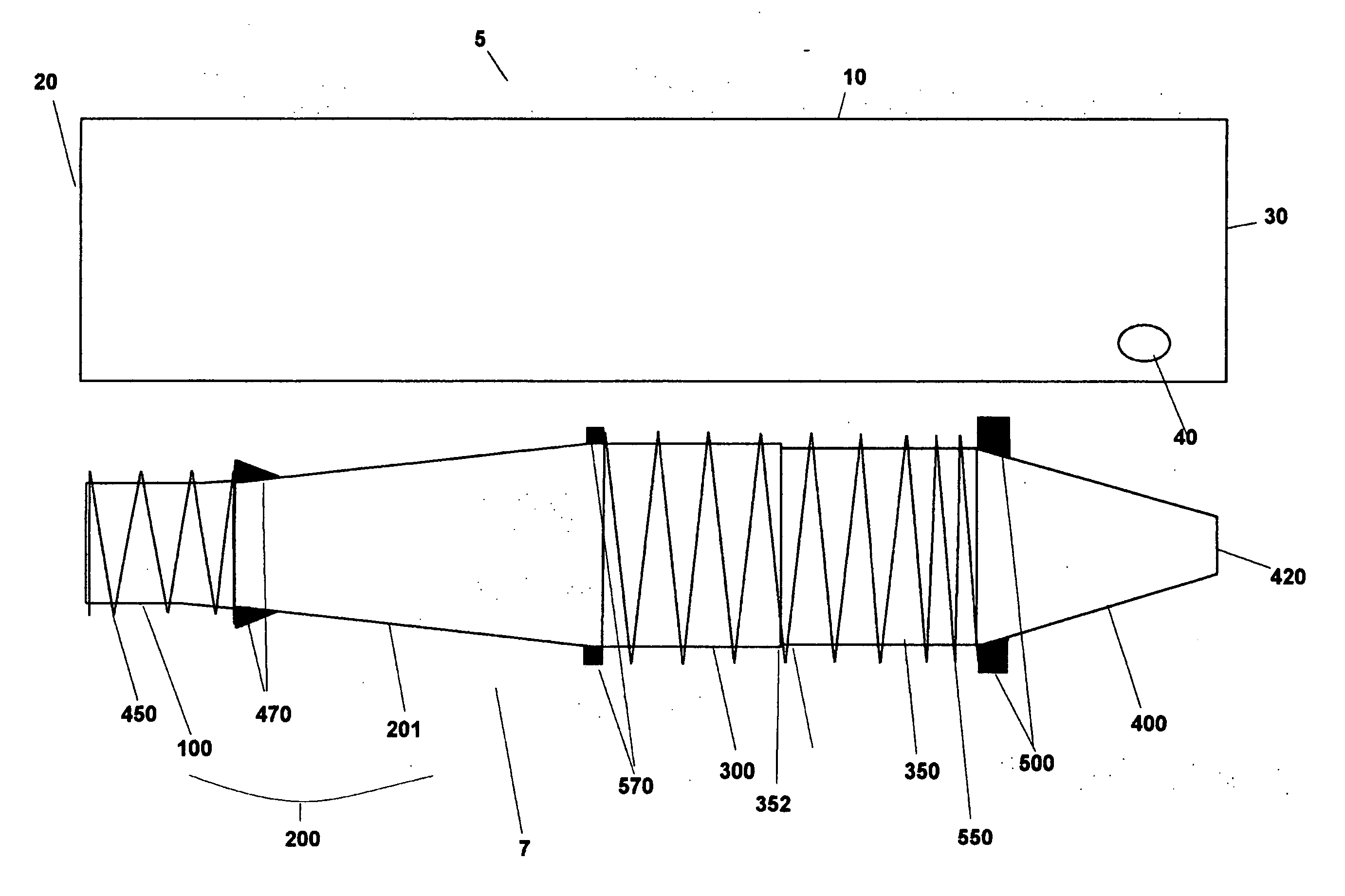
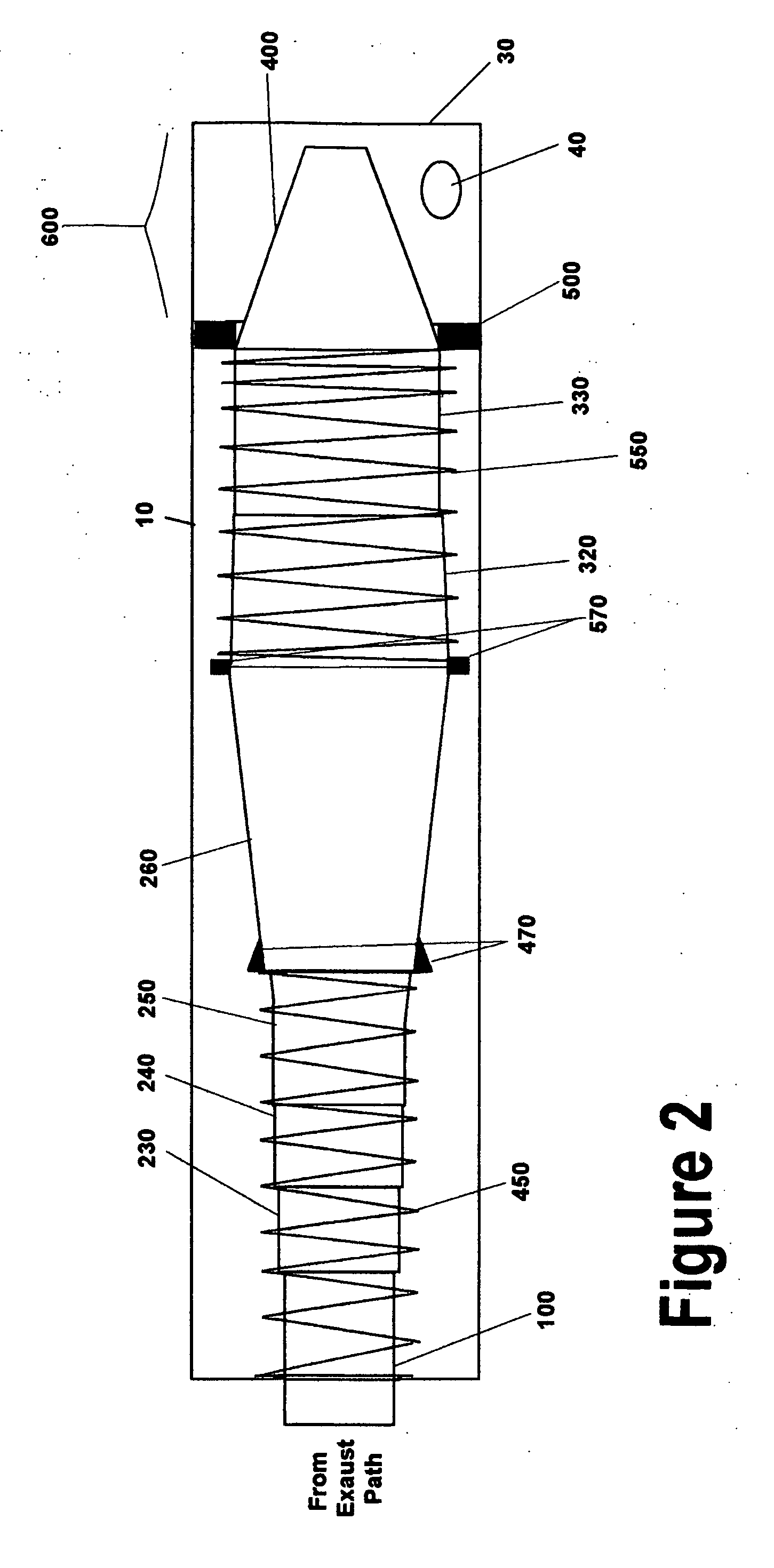
[0044] The invention is generally described as exhaust system that automatically, dynamically changes length over a range of engine speeds. This change in “tuned length”, as often referred to in the industry, will produce maximum power output over a much wider range of engine speed than can be achieved with a static exhaust system. Put another way, the variation in the “tuned length” of the exhaust will maintain operation of the engine at or near the peak of its power curve over a wide range of engine RPMs.

[0045] The design and dimensions of the exhaust system described herein are for an exemplary preferred embodiment, specifically a displacement glow ignition two-stroke motor as commonly found in remote control cars, boats and airplanes. With the appropriate changes in geometry, the design can be applied to larger displacement two-stroke, four stroke, and glow ignition two stroke motors or spark ignition motors of any size. Applications may include, but are not limited to: off-roa...


PUM


Abstract

A method and apparatus, for adjusting an exhaust, having an at least one body element with a housing member having an at least one exhaust outlet. An at least one exhaust element is contained within the at least one body element with an at least one slip section and an at least one spring member. An at least one pressure regulating member extends and is slidingly held between the at least one body element and the at least one exhaust element. The pressure regulating member separates a pressure chamber section within the housing, wherein the pressure regulating member is pressed against the at least one spring member by pressures built up by exiting exhaust gasses in the pressure chamber resulting in a variation in the length of the exhaust system.

Description

CROSS REFERENCE TO RELATED APPLICATIONS [0001] This application claims the priority of U.S. provisional patent applications 60 / 656,091, filed Feb. 25, 2005 and 60 / 683,773, filed May 24, 20005, which are incorporated herein by reference.FIELD OF THE INVENTION [0002] The invention relates to an apparatus and system for automatically adjusting the tuned length of an exhaust system. More specifically, an exhaust system that uses variations in the speed of the engine and corresponding exhaust gasses to adjust the length of the exhaust system. BACKGROUND OF THE INVENTION [0003] It is a well-established concept in engine design that an increase the performance of an internal-combustion, reciprocating engine can be achieved through various improvements in the exhaust system. One way to improve an exhaust system has been to utilize pressure variations developed within an exhaust system, typically through changing backpressure and resonance, to supplement the control of gases moving within th...

Claims


Application Information

Patent Timeline
Patent Type & Authority Applications(United States)
IPC IPC(8): B05B12/00
CPCF01N1/165F01N13/1827F01N2390/02F02D9/04F01N2470/14F01N2470/18F01N2470/24F01N2470/08
Inventor MASLAR, DAVID
Owner MASLAR DAVID
Learn More