
Rolling bearing, grease supply system, sprindle unit, grease supply method, and grease supply program

Active Publication Date: 2006-10-26
NSK LTD
View PDF2 Cites 38 Cited by
  • Summary
  • Abstract
  • Description
  • Claims
  • Application Information

AI Technical Summary

Benefits of technology

[0101] the cooling means cools the stator and also c

Problems solved by technology

When the bearing is run at a high speed in the initial stage of the grease filling without the running-in trial of the grease, an abnormal heat generation is caused owing to the jamming or the churning resistance of the grease.
In the case where the number of revolution is extremely high, the seizure of the bearing is caused in an early stage because the grease is degraded in a short time or the formation of the oil film is insufficient.
In this case, since the above unit supplies the additional grease after the abnormality was generated in the bearing, it is possible that the bearing has already been damaged at a point of time when the additional grease is supplied.
Thus, there exists such a problem that the grease is filled excessively in the bearing.
As a result, the grease supply executed every predetermined interval is ineffective when the using conditions are not severe, which results in a wasteful increase in the supply number of times. In addition, the grease supplied excessively in response to the increase in the supply number of times makes a bearing temperature unstable.
Therefore, when the stopped bearing is operated again, the churning resistance of the grease is increased by the added grease and thus a sudden temperature rise is caused.
However, when the grease is exhausted in the grease tank that stores the grease to be supplied to the mechanical fixed- displacement piston pump, the grease is not supplied from the mechanical fixed-displacement piston pump.
Thus the lubrication failure is generated in the bearing and then the bearing is seized up.
Therefore, there was such a problem that the lubrication failure is generated in the bearing and then the bearing is seized up.
As a result, there existed the problem that it is difficult to execute the stable discharge of the grease.
Also, in the grease supply system 1670, a residual pressure still remains for a long time in the grease remained in the piping from the grease pressurizing portion to the bearing, and thus such grease tends to flow though an mount of the grease is minute.
As a result, there existed the problem that it is impossible to discharge the grease in a fixed quantity.
However, there is a limit to the lifetime of the grease even if such management is applied, and thus the long lifetime similar to that obtained when the oil air lubrication or the oil mist lubrication is applied cannot be obtained.
Thus, it is possible that the seizure of the bearing is brought about due to the oxidative degradation of the grease or the defective formation of the oil film.
When a bearing temperature becomes 70 to 80° C., a kinetic viscosity of the base oil is 6 to 8 mm2 / s and thus it is difficult to keep the oil film.
Also, in the spindle unit of the machine tool, if the cutting fluid enters into the bearing in the spindle unit from the outside, a lubricating performance of the spindle bearing is deteriorated to cause the seizure of the bearing.
However, these cutting fluid entering preventing means cannot completely prevent the entering of the cutting fluid.
However, in JP-UM-A-4-90770, there existed the problem that the cutting fluid enters into the inside of the spindle unit.
Also, in JP-A-2002-239867, according to the method of exhausting the extraneous matter from the drain hole by the rotation of the spindle, there existed the problem that the exhausting capability is lowered when the rotation speed is slow.
Thus, there existed the problem that either the seizure of the bearing occurs or the maintenance such as exchange, decomposition / rinsing, etc. of the bearing is needed.
In particular, many instances were found in the grease lubrication where the grease that was sealed once is rinsed out by the cutting fluid when the cutting fluid enters into the bearing and thus the bearing is damaged.
As a result, there existed the problem that it is difficult to continue to supply the lubricant for a long time.
Besides, there also existed the problem that, when the exhaust of the lubricant to the outside of the bearing unit 1701, 1702 is performed by the suction applied from the outside of the bearing unit, it is difficult to remove completely the lubricant in the bearing unit 1701, 1702.
Therefore, the grease does not reach the supply hole in the outer ring and thus the grease cannot be supplied to the inside of the bearing.
Therefore, the grease is not supplied from the supply hole in the outer ring to the inside of the bearing.

Method used


Image

  • Rolling bearing, grease supply system, sprindle unit, grease supply method, and grease supply program
  • Rolling bearing, grease supply system, sprindle unit, grease supply method, and grease supply program
  • Rolling bearing, grease supply system, sprindle unit, grease supply method, and grease supply program

Examples


tenth embodiment

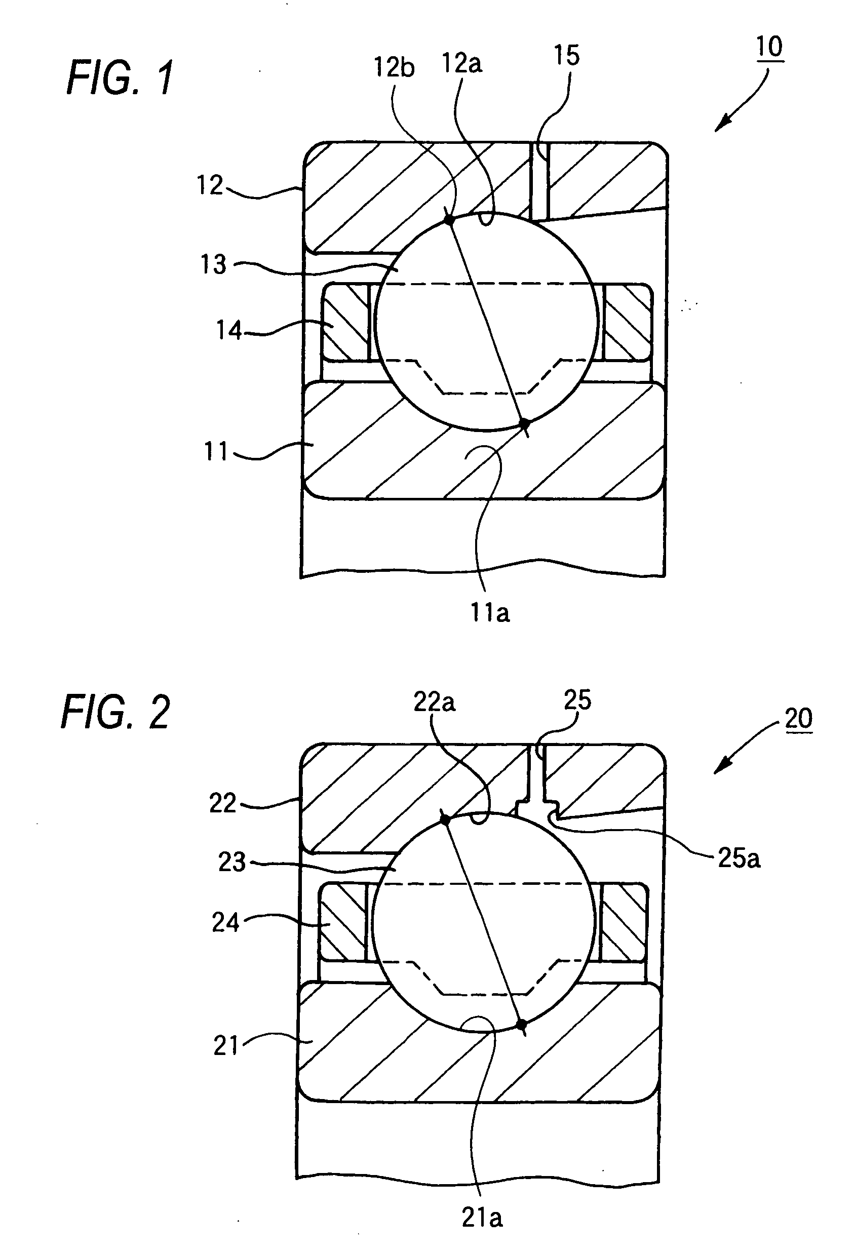
[0374] A single row cylindrical roller bearing 100 of a tenth embodiment according to the present invention shown in FIG. 10 includes an inner ring 101, an outer ring 102, a plurality of cylindrical rollers 103 arranged between an inner ring raceway 101a of the inner ring 101 and an outer ring raceway 102a of the outer ring 102, and a cage 104 guided by the outer ring.

[0375] In the present embodiment, two supply holes 105 each serving as a grease supply system (or grease supply mechanism) that passes through the outer ring 102 in the radial direction are provided to the outer ring 102, when viewed along the axial direction. Each supply hole 105 is opened toward the portion between both end faces of the cylindrical rollers 103 and the guide surface of the cage 104 in the axial direction. A groove 105b is provided on the outer diameter surface of the outer ring in double rows.

[0376] Although not shown, such a configuration may be employed that a supply hole is provided, when viewed ...

eleventh embodiment

[0378] A single row cylindrical roller bearing 110 of an eleventh embodiment according to the present invention shown in FIG. 11 includes an inner ring 111, an outer ring 112, a plurality of cylindrical rollers 113 arranged between an inner ring raceway 111a of the inner ring 111 and an outer ring raceway 112a of the outer ring 112, and a cage 114 guided by the outer ring.

[0379] In the present embodiment, a supply hole 115 serving as a grease supply system (or grease supply mechanism) that passes through the outer ring 112 in the radial direction is provided in a center portion of the outer ring 112 in the axial direction. The supply hole 115 is formed into a taper shape, which is suited to a taper shape of a top end of a nozzle 260 to shoot the grease and in which a diameter is reduced gradually from the outer diameter surface side to the inner diameter surface side. That is, the supply hole 115 is formed as a frustum-of-circular-cone space. The supply hole 115 is opened toward th...

twelfth embodiment

[0381] A single row cylindrical roller bearing 120 of a twelfth embodiment according to the present invention shown in FIG. 12 includes an inner ring 121, an outer ring 122 having two collars 122b, cylindrical rollers 123 arranged between an inner ring raceway 121a of the inner ring 121 and an outer ring raceway 122a of the outer ring 122, and a cage 124 guided by the outer ring.

[0382] The cylindrical rollers 123 are arranged rollably along the outer ring raceway 122a formed between the collars 122b acting as inner peripheral surfaces of the outer ring 122 and the inner ring raceway 121a formed on an outer peripheral surface of the inner ring 121. A clearance portion 122c as a concave portion is provided to both end portions of the outer ring raceway 122a in positions that oppose to edge portions 123a of the cylindrical rollers 123 to avoid the interference with the edge portions 123a.

[0383] In the present embodiment, a supply hole 125 serving as a grease supply system (or grease ...


PUM

PropertyMeasurementUnit
Lengthaaaaaaaaaa
Diameteraaaaaaaaaa
Diameteraaaaaaaaaa

Abstract

A spindle unit comprises a rolling bearing including an outer ring having an outer ring raceway on an inner peripheral surface, an inner ring having an inner ring raceway on an outer peripheral surface, and rolling elements provided rollably between the outer ring raceway and the inner ring raceway, whereby a spindle is borne rotatably in a housing, and a grease supply system for supplying a grease to an inside of the rolling bearing, wherein the grease supply system supplies the grease such that a supply amount in one shot is set to 0.004 cc to 0.1 cc.

Description

TECHNICAL FIELD [0001] The present invention relates to a rolling bearing for supporting a spindle of a machine tool, a high speed motor, or the like, a grease supply system for lubricating the rolling bearing with grease, and a spindle unit using the same. Also, the present invention relates to a grease supply method and a grease supply program of supplying the grease. BACKGROUND ART [0002] In order to improve a machining precision, the good characteristics in regarding to the vibration, the noise, etc. are required of the bearing for the machine tool spindle. Also, the grease lubrication that is easy to handle and is effective in an environmental aspect and a cost aspect is required of the bearing for the machine tool spindle to attain a high-speed running performance and a long lifetime. [0003] It is normal that the grease-lubricated rolling bearing for use in the machine tool spindle is lubricated merely with the initially sealed grease not to generate a heat. When the bearing i...

Claims


Application Information

Patent Timeline
IPC IPC(8): F16C19/00B23Q11/12F16C33/66
CPCB23Q11/122F16C19/54F16C33/6625B23Q11/123F16C2322/39
Inventor MATSUYAMA, NAOKIAZUMI, SABUROUKOIWA, YUUAOKI, MITSUHOMORITA, YASUSHIINAGAKI, YOSHIFUMISUGITA, SUMIOINABA, KENYAKURA, KENJI
Owner NSK LTD
Learn More