
Video hologram and device for reconstructing video holograms using wavefront at eyes

a wavefront and video hologram technology, applied in the field of video hologram and video hologram and a device for reconstructing video holograms, can solve the problems of voluminous and heavy elements, limited range of applications, and gradual limitation of the usable extent of reconstruction, and achieve the effect of large viewing angles

Inactive Publication Date: 2006-10-26
SEEREAL TECHNOLOGIES
View PDF13 Cites 37 Cited by
  • Summary
  • Abstract
  • Description
  • Claims
  • Application Information

AI Technical Summary

Benefits of technology

The invention is about a device that can reconstruct video holograms with controllable openings. The device has a viewing window that allows a viewer to see a three-dimensional scene. The viewer's eye is positioned in the viewing window. The device can also have multiple viewing windows, allowing multiple viewers to see the reconstructed scene. The invention also allows for efficient generation of holographic reconstructions of spatially extended scenes through controllable displays, which can be used in various applications. The invention has several technical effects, including improved viewing angles, reduced data requirements, and improved efficiency in generating holograms reconstructions.

Problems solved by technology

Due to their great depth, these elements are voluminous and heavy.
It is difficult to miniaturize them, so that their range of applications is limited.
The usable extent of the reconstruction is thus gradually limited.
However, this is currently not feasible in the form of displays with controllable openings, as discussed in, for instance, U.S. Pat. No. 6,831,678 issued to Travis on Dec. 14, 2004 entitled “Autostereoscopic display”, the contents of which are hereby incorporated by reference.
Fourier transformations of data flows of this magnitude exceed the capabilities of today's computers by far and do thus not allow holograms to be calculated based on local computers.
However, transmitting such an amount of data through data networks is presently unfeasible for normal users.
However, this partly nullifies the reduction in the number of computations.
The disadvantages of the known methods can be summarized as follows: Arrangements with acousto-optical modulators are too voluminous and cannot be reduced to dimensions known from state-of-the-art flat displays; video holograms generated using the tiling method are two-stage processes which require enormous technical efforts and which cannot easily be reduced to desktop dimensions; and arrangements based on SLM with controllable openings are too small to be able to reconstruct large scenes.
There are currently no large controllable SLM with extremely small pitches, which would be needed for this, and this technology is further limited by the computer performance and data network bandwidth available today.

Method used


Image

  • Video hologram and device for reconstructing video holograms using wavefront at eyes
  • Video hologram and device for reconstructing video holograms using wavefront at eyes
  • Video hologram and device for reconstructing video holograms using wavefront at eyes

Examples


Embodiment Construction

[0030] A device for reconstructing video holograms comprises the hologram-bearing medium, a sufficiently coherent, real or virtual, point or line light source and an optical system. The video hologram-bearing medium itself consists of cells which are arranged in a matrix or in an otherwise regular pattern with at least one opening per cell, the phase or amplitude of said opening being controllable. The optical system for reconstructing the video hologram can be realized by an optical imaging system known in the art, consisting of a point or line laser or a sufficiently coherent light source.

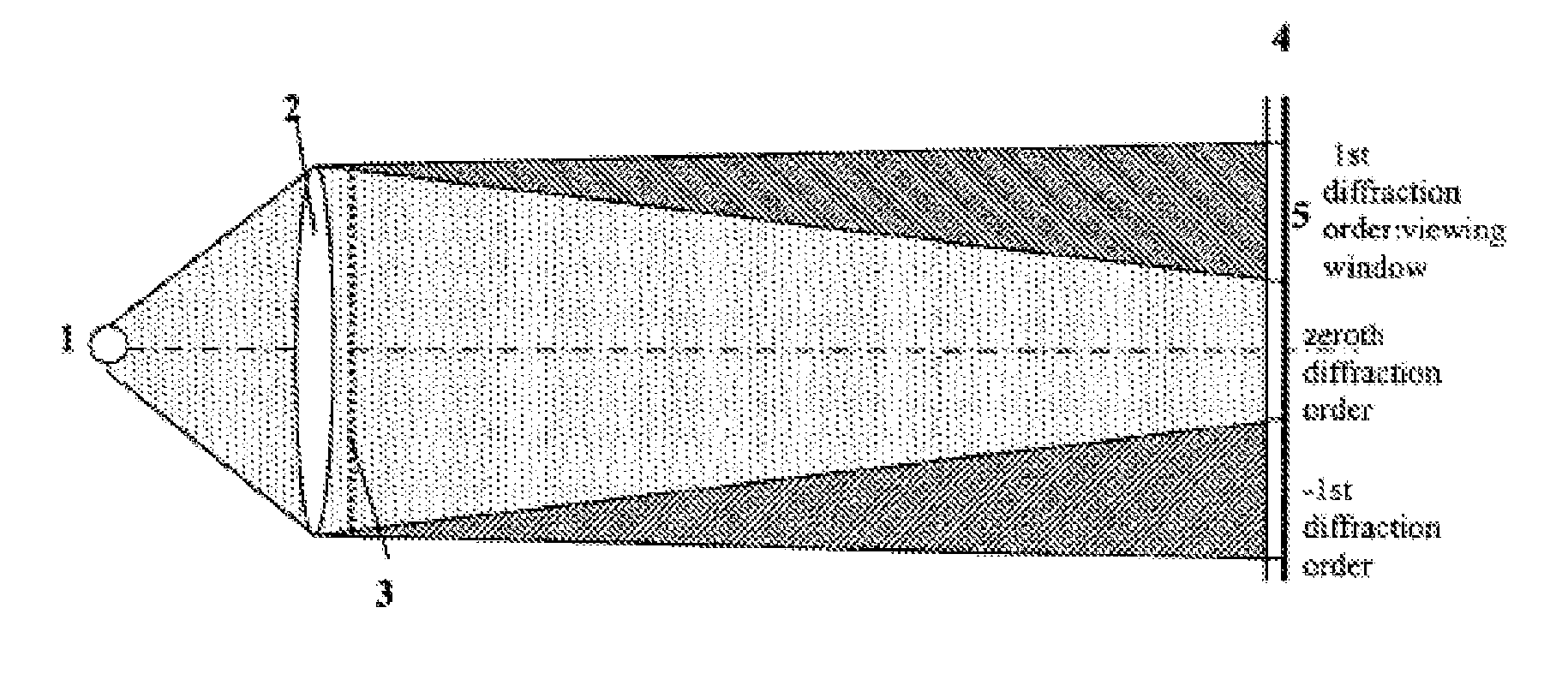
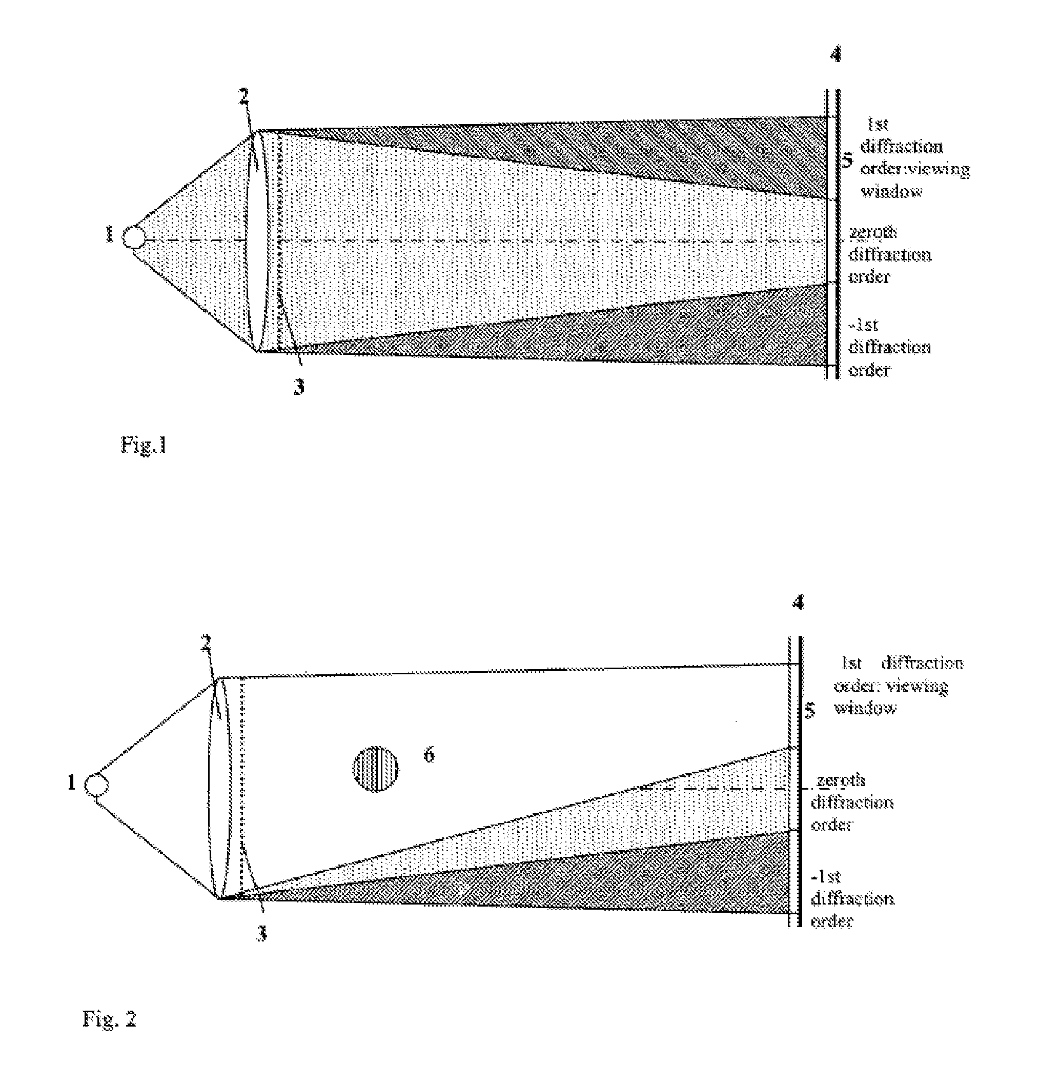
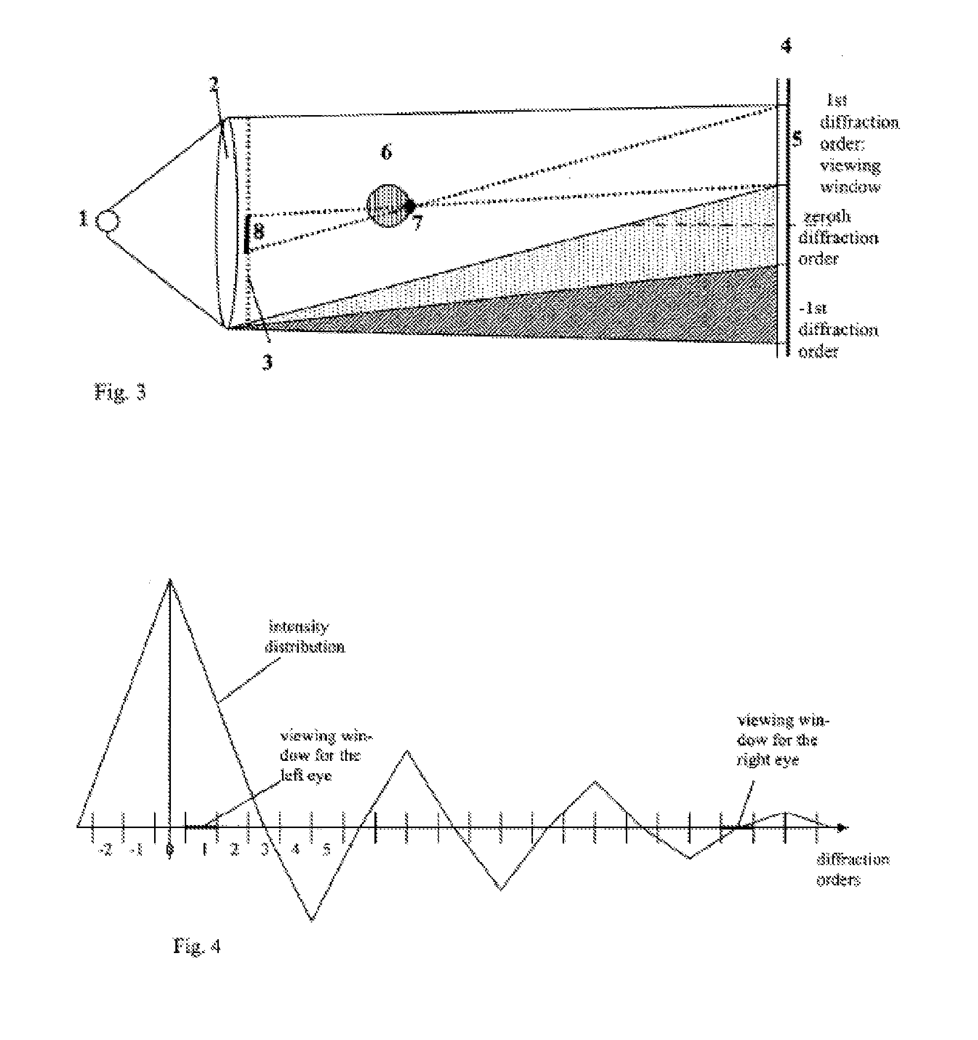
[0031]FIG. 1 shows the general arrangement of a video hologram and its reconstruction. A light source 1, a lens 2, a hologram-bearing medium 3 and a viewing plane 4 are arranged one after another, seen in the direction of the propagating light. The viewing plane 4 corresponds with the Fourier plane of the inverse transform of the video hologram with the diffraction orders.

[0032] The light sourc...


PUM


Abstract

A method of computing a hologram by determining the wavefronts at the approximate observer eye position that would be generated by a real version of an object to be reconstructed. In normal computer generated holograms, one determines the wavefronts needed to reconstruct an object; this is not done directly in the present invention. Instead, one determines the wavefronts at an observer window that would be generated by a real object located at the same position of the reconstructed object. One can then back-transform these wavefronts to the hologram to determine how the hologram needs to be encoded to generate these wavefronts. A suitably encoded hologram can then generate a reconstruction of the three-dimensional scene that can be observed by placing one's eyes at the plane of the observer window and looking through the observer window.

Description

CROSS REFERENCE TO RELATED APPLICATIONS [0001] This application is a divisional application of U.S. patent application Ser. No. 10 / 534,877 filed by A. Schwerdtner on May 12, 2005 entitled “Video Hologram and Device for Reconstructing Video Holograms”, the contents of which are hereby incorporated by reference. [0002] U.S. patent application Ser. No. 10 / 534,877 application is, in turn, related to, and claims priority from, PCT patent application PCT / DE03 / 03791 filed on Nov. 11, 2003 and to German Patent application DE 10253292.3 filed on Nov. 13, 2002, the contents of both of which are hereby incorporated by reference.FIELD OF THE INVENTION [0003] The present invention relates to a video hologram and a device for reconstructing video holograms having an optical system that includes at least one light source, a lens and a hologram-bearing medium composed of cells arranged in a matrix or an otherwise regular pattern, with at least one opening per cell, and with the phase or amplitude o...

Claims


Application Information

Patent Timeline
Patent Type & Authority Applications(United States)
IPC IPC(8): G03H1/22G03H1/08
CPCG03H1/08G03H1/2286G03H1/2294G03H2001/0858G03H2001/2236G03H2210/30G03H2001/2271G03H2222/22G03H2222/34G03H2226/05G03H1/16G03H2001/2242G03H1/00
Inventor SCHWERDTNER, ARMIN
Owner SEEREAL TECHNOLOGIES
Learn More