Perpetual motion comptrollers & energy molecule splitters

a technology of energy molecule splitter and comptroller, which is applied in the direction of dynamo-electric components, dynamo-electric machines, electrical apparatus, etc., can solve the problems of 9,500watt generator, 14-hp motor is not sufficient to operate a 12-volt alternator, and device also makes improper use of component parts, so as to increase the energy within the system and eliminate waste or emissions

Inactive Publication Date: 2006-10-26
BAILEY RUDOLPH SR
View PDF1 Cites 8 Cited by
  • Summary
  • Abstract
  • Description
  • Claims
  • Application Information

AI Technical Summary

Benefits of technology

[0009] In order to be able to described the present invention briefly, according to a typical embodiment. We must first explain what we at JESUS & Bailey call the “Science of Perpetual Motion Machine”. In order to develop perpetual motion and do useful work, one must first be able to recycle the energy within a system or device, resulting in no waste or emissions. Next one must be able to split each energy molecule and take one molecule, and make two as one recycle said energy. In so doing one will be able to generate enough new energy within the system, to overcome what will be lost due to friction and heat, and also to do useful work. Said new science is possible in a DC battery operated system.
[0010] Let us consider a 24-volt-DC circuit comprising two 12volt deep cycle batteries connected to give 24-volts. Additionally let us consider a 24-volt-DC motor being operated by said batteries. The motor will convert the electrical energy from the battery into turning motion. Said turning motion with

Problems solved by technology

Frost's invention falls short of its intended goal, as the device is inoperable, and violates the second law of thermodynamics, and the laws of energy conversion.
The device also makes improper use of component parts, hence the said comptroller would be of no value in facilitating perpetual motion of Frost's device.
In addition to that Frost would also be using an automobile type alternator to recharge two discharged batteries, said alternators are not designed to charge a discharged battery, such charging must be accomplished by using a AC to DC trickle

Method used


Image

  • Perpetual motion comptrollers & energy molecule splitters
  • Perpetual motion comptrollers & energy molecule splitters
  • Perpetual motion comptrollers & energy molecule splitters

Examples


Embodiment Construction

Description

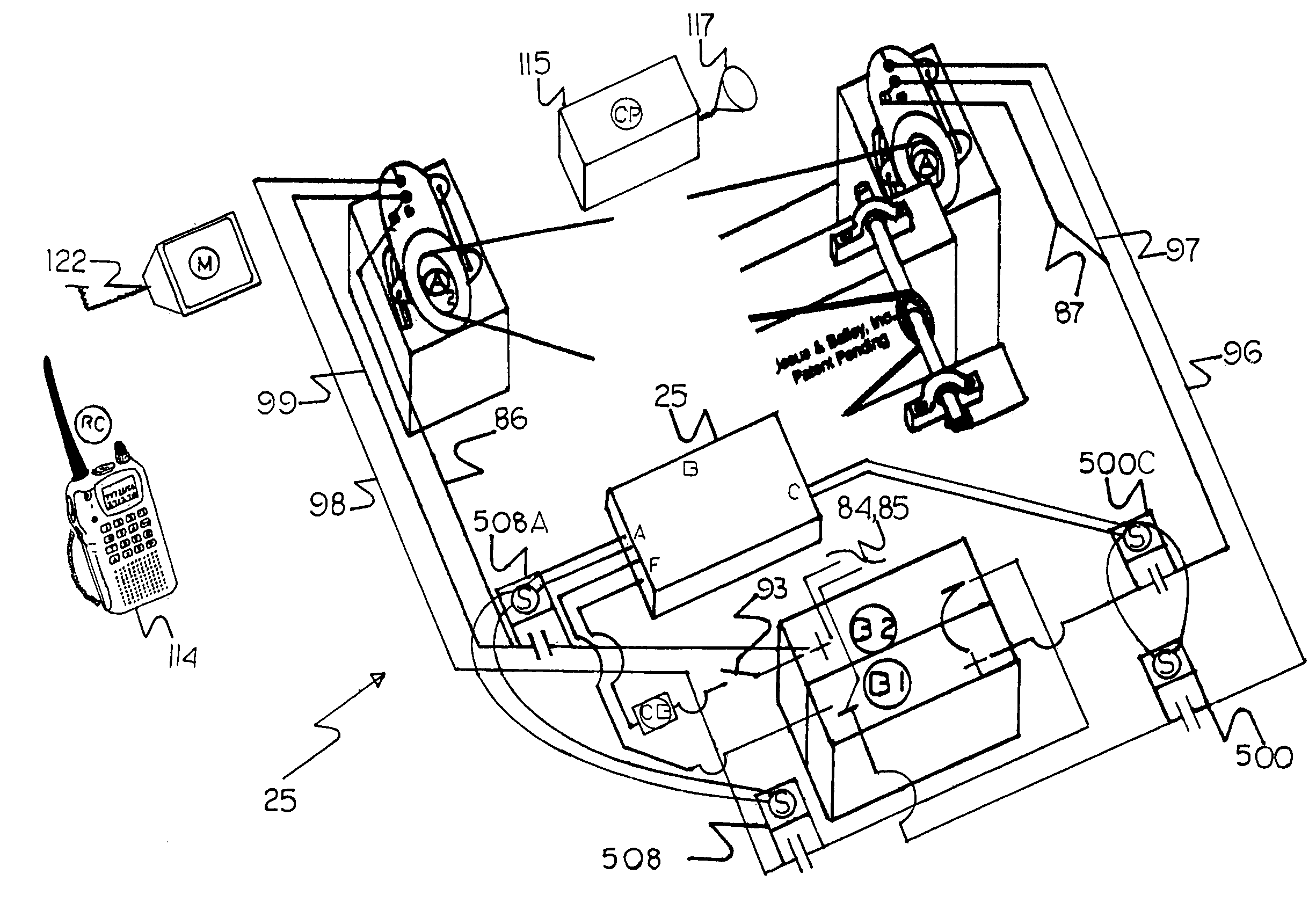
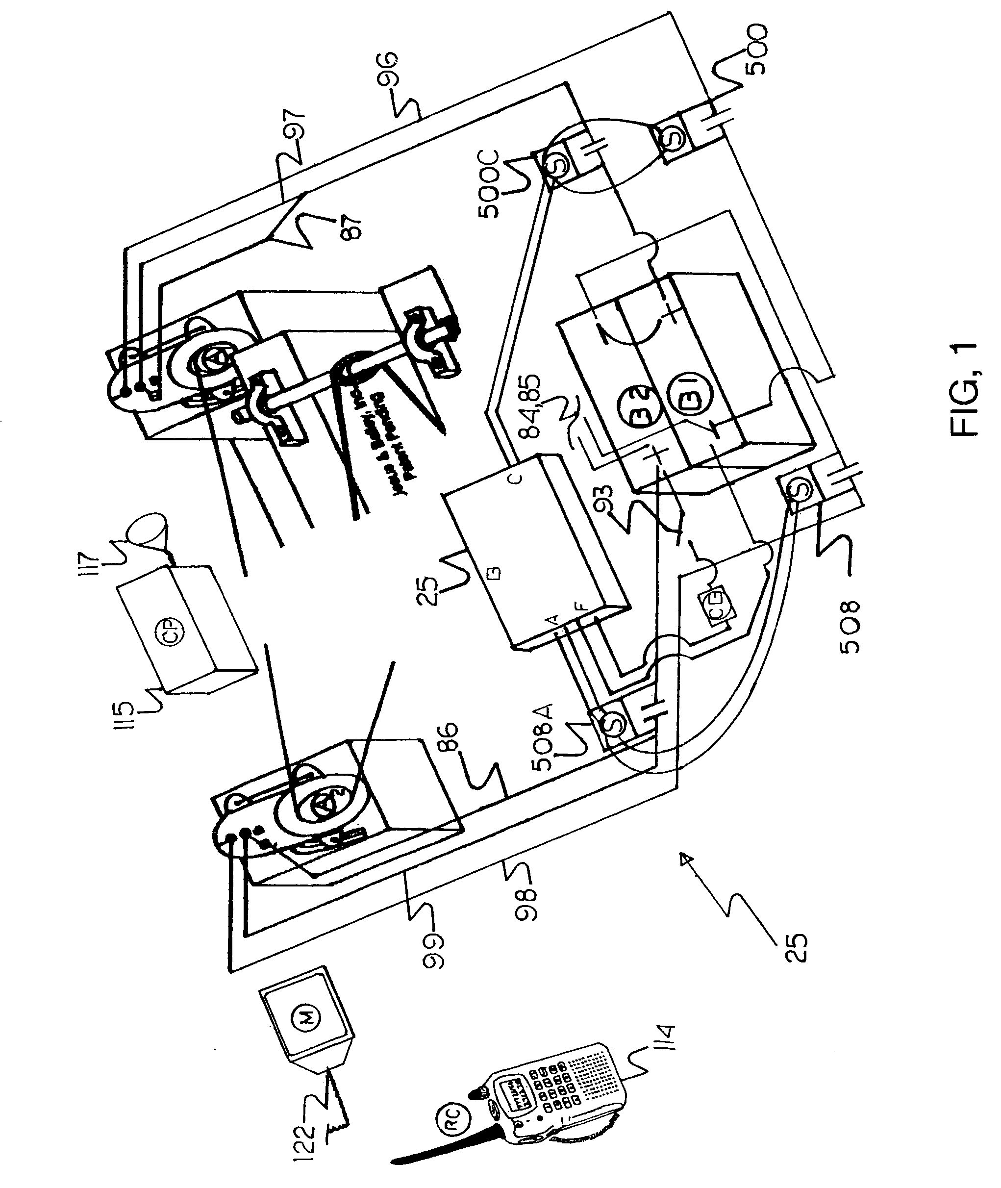
[0058] Referring now to the drawings and, in particular, to FIG. 1 wherein there is illustrated a typical embodiment of a perpetual motion comptroller & energy molecule splitter 25. The present version of the invention 25 which casing is constructed non-conductive materials such as plastic or fiber glass, with a removable cover. FIG. 1 shows how comptroller 25 inter-relates with its associate component parts which are covered in co-pending application Ser. No. 10 / 811,382, and are not part of this application.

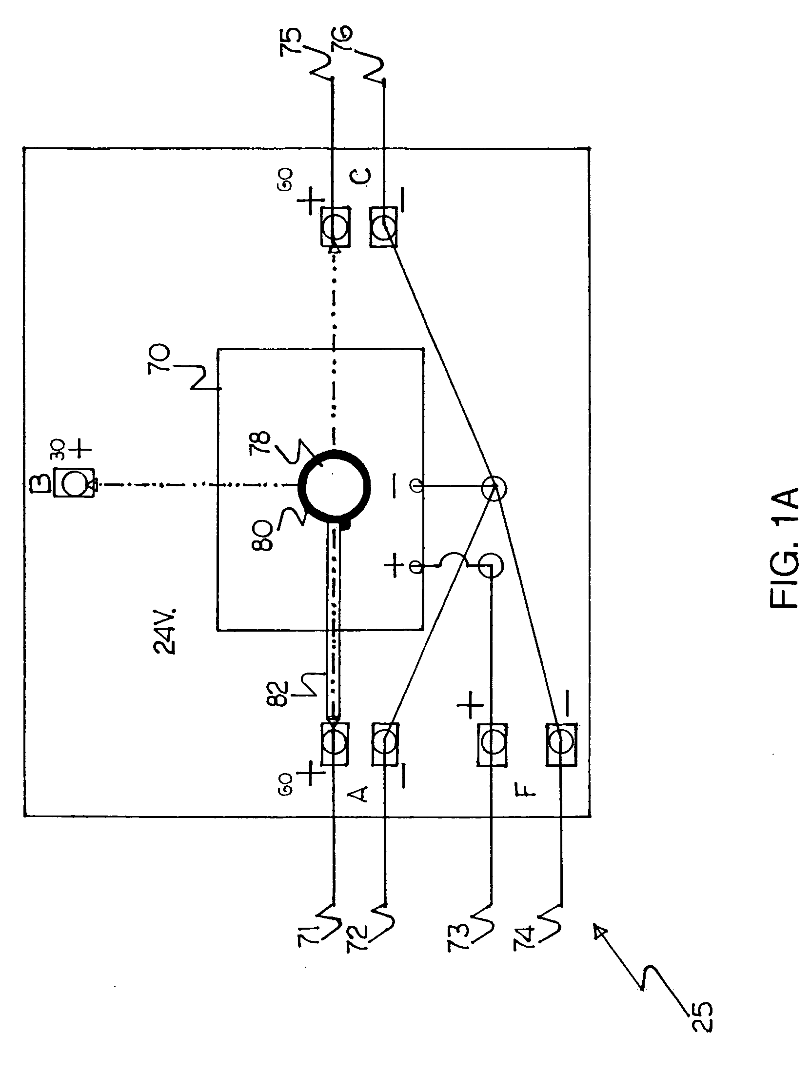
[0059] Referring to now to FIG. 1A, wherein is illustrated the internals of comptroller 25, with a main control board 70, which controls the timing and switching of the 24-volt power supply to the external alternator solenoids. Pointer 82, is insulated and moves the 24-volts to the output terminals A, B, & C. Terminal F, is 24-volt feed intake to main control board 70.

[0060] Referring again to FIG. 1, when switch 93 is closed 24-volts goes to Comptroller 25, via w...


PUM


Abstract

A method to convert a battery operated device into a perpetual motion machines has been disclosed. A method for splitting an energy molecule in two and making two molecule from the one while recycling the energy has disclosed. The increased energy is used to offset that which will be loss due to friction, and to do useful work. A molecule splitter and comptroller is used to control the refurbishing of said batteries one at a time, and to rest the drive motor, so as to prevent the device from coming to a stop. Since the method used does not create new energy, but generate new energy by splitting the energy molecule, it does not violate the laws of energy conversion, or the laws of thermodynamics.

Description

DESCRIPTION OF RELATED APPLICATIONS [0001] This Application is a continuation-in-part of co-pending application Ser. No. 10 / 811,382 filled on Mar. 27, 2004. This application also claims the benifit of PPA Ser. No. 60 / 644,725, filed on Jan. 18, 2005.BACKGROUND [0002] This version of the invention Is concerned with the field of control devices used to control perpetual motion machines, and energy molecule splitters that can be used to increase the energy within a system. More specifically, this version of the invention is concerned with prior art control devices and technology using timing controls, and computer hardware and software including alpha-digital or voice-sound commands or instructions, for a new and unintended, and unforeseen use, to produce perpetual motion which is believed to be both scientifically and practically impossible. PRIOR ART [0003] An example of said control devices can be seen as is exemplified in U.S. Pat. No. 5,804,948 System for Zero Emission Generation o...

Claims


Application Information

Patent Timeline
IPC IPC(8): H02K7/18F03G7/08F02B63/04
CPCF03G7/10
Inventor BAILEY, RUDOLPH SR.
Owner BAILEY RUDOLPH SR
Why Eureka
Try Eureka