
Paper roll edge trimming method and apparatus

a paper roll and edge trimming technology, applied in metal working equipment, transportation and packaging, thin material processing, etc., can solve the problems of paper adjacent to the end of the roll being rendered unusable or undesirable for the intended use of the paper web of the roll, web breakage, costing time and money to process the roll of paper web

Inactive Publication Date: 2006-10-26
VERSO PAPER
View PDF3 Cites 4 Cited by
  • Summary
  • Abstract
  • Description
  • Claims
  • Application Information

AI Technical Summary

Benefits of technology

"The present invention provides a way to safely and precisely remove a layer of paper from the end of a roll without needing to unwind the paper from the roll. This is done using a cutter that can move along multiple axes relative to the roll. The cutter is adjusted to remove only the damaged paper while maximizing the depth of cut into the roll. This method and apparatus make it easier to manage and use rolls of paper that may have damaged edges."

Problems solved by technology

In storage, during handling, etc., the ends of these rolls of paper are subjected to becoming damaged, contaminated, wetted or subjected to other destructive treatment which results in the paper adjacent an end of the roll being rendered unusable or undesirable for the intended use of the paper web of the roll.
Such bonded layers of the paper web tend to cause the paper web to resist unwinding such that the web breaks as it is unwound from the roll.
Each such break requires a “shut-down” of the conversion machine to re-thread the web into the machine, costing time and money to process the roll of paper web.
Such devices create potentially hazardous amounts of paper dust, and in some instances are inherently hazardous to operate or expensive to protect against operator injury.
Other prior art devices are deficient with respect to control over the cutting operation, resulting in loss of valuable paper or inadequate removal of paper from the end of the roll.
Moreover, known prior art devices tend to create a less than square end of the cut roll, often leaving ridges and valleys defined in the cut end of the roll.

Method used


Image

  • Paper roll edge trimming method and apparatus
  • Paper roll edge trimming method and apparatus
  • Paper roll edge trimming method and apparatus

Examples


Embodiment Construction

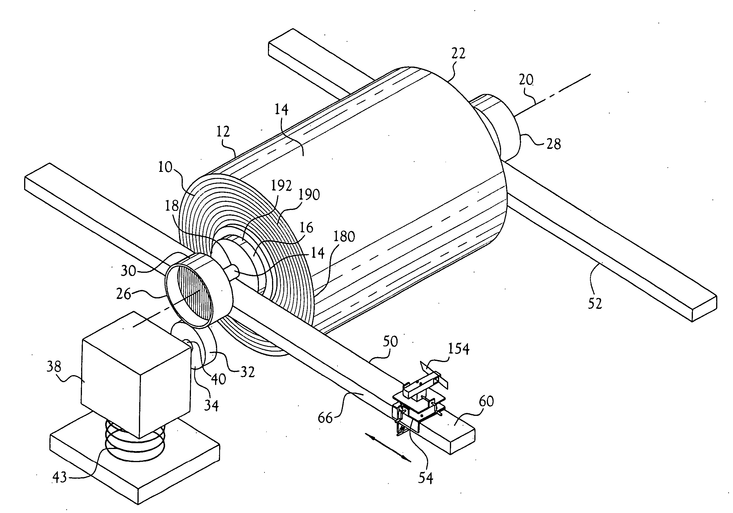
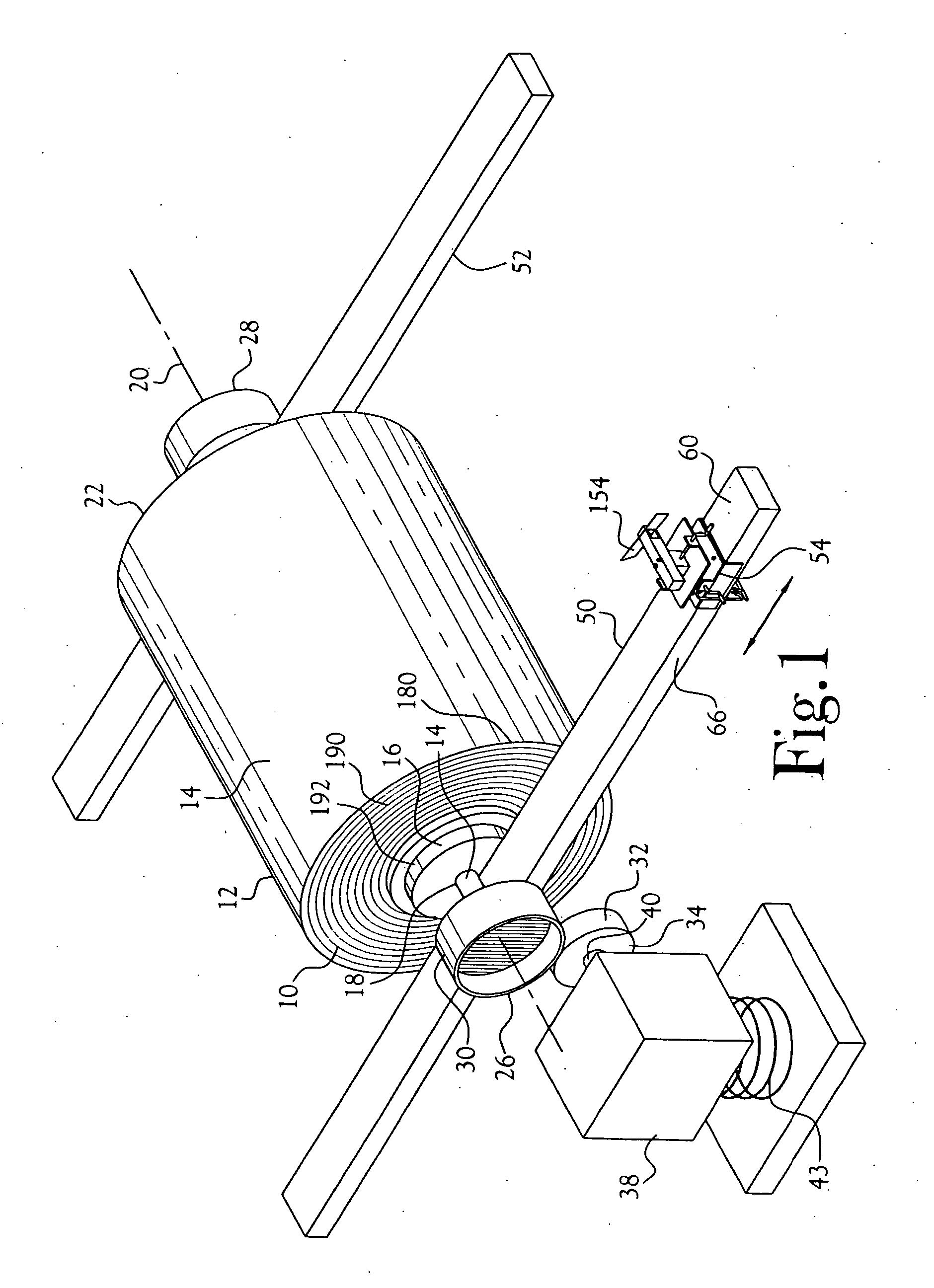
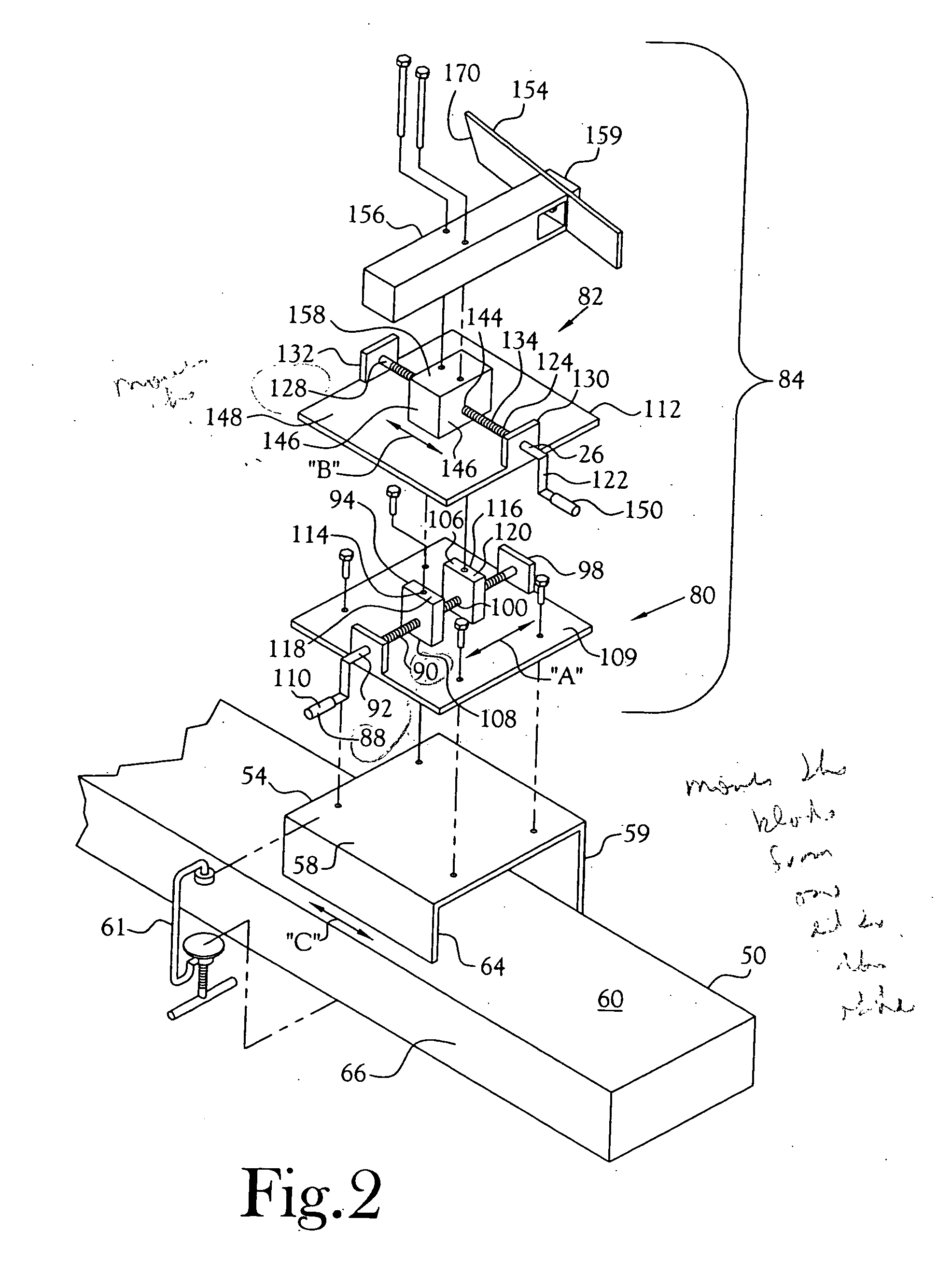
[0014] With reference to FIGS. 1 and 2, in one embodiment of the present invention, there is provided apparatus for severing or cutting away a selected portion of an end 10 of a roll 12 of paper web 14. The depicted roll includes a spool 16 upon which the paper web is wound to generate the roll. The depicted spool is fitted with a shaft 18 which extends through the central axis of the spool and beyond the opposite ends 10 and 22 of the depicted roll to define a rotational axis 20 for the roll.

[0015] As depicted in FIG. 1, each end of the shaft which projects beyond the respective ends of the roll is provided with a disc 26,28 oriented substantially perpendicular to the rotational axis of the shaft / roll and fixed to the shaft for rotation of the shaft upon rotation of the disc. As also depicted in FIG. 1, the disc 26 includes an outer circumferential surface 30. For rotation of the roll about its rotational axis, the outer circumferential surface of the disc is engaged by the outer ...


PUM

PropertyMeasurementUnit
angleaaaaaaaaaa
angleaaaaaaaaaa
distancesaaaaaaaaaa

Abstract

The present invention is directed to a method and apparatus for precisely controlled and operator safe removal of a desired width of layered paper from the end of a roll or paper web, as for example a paper roll having one or both ends damaged, employing a compound mount for a knife-blade type cutter which is selectively adjustable along multiple axes relative to the rotational axis and width of the paper roll as the roll is rotated independently of the cutter and without unwinding the paper web from the roll. In accordance with one aspect of the present invention, only that quantity of paper web, which is damaged, is removed while maximizing the depth of cut radially into the roll by the cutter.

Description

CROSS-REFERENCE TO RELATED APPLICATIONS [0001] Not Applicable STATEMENT REGARDING FEDERALLY SPONSORED RESEARCH OR DEVELOPMENT [0002] Not Applicable FIELD OF INVENTION [0003] This invention relates to trimming the ends of rolls of paper or the like, such as for purposes of sizing the width of the roll or removal of damaged paper from the end of the roll. BACKGROUND OF INVENTION [0004] Formed paper webs are commonly collected in rolls for storage, transport and otherwise handling in the course of conversion of the web into some desired form. In storage, during handling, etc., the ends of these rolls of paper are subjected to becoming damaged, contaminated, wetted or subjected to other destructive treatment which results in the paper adjacent an end of the roll being rendered unusable or undesirable for the intended use of the paper web of the roll. Rolls of paper web may be relatively small, but commonly the web is collected in a jumbo roll which weighs many hundreds of pounds. [0005]...

Claims


Application Information

Patent Timeline
Patent Type & Authority Applications(United States)
IPC IPC(8): B26D1/00B26D1/04B26D3/16B65H19/10
CPCB26D1/04B26D3/166B65H2701/1849B65H19/105B65H2301/41734B26D2210/11Y10T83/04Y10T83/202Y10T83/7145
Inventor WALSH, JOSEPH THOMASSMART, RUSSELL GEORGE
Owner VERSO PAPER
Learn More