
Needle-less fluid delivery assembly and error prevention system

a fluid delivery and assembly technology, applied in the field of fluid delivery, can solve the problems of increasing the risk of accidental needle sticks, increasing the acuity of patient illness, and infecting healthcare professionals

Inactive Publication Date: 2006-10-19
WIZARD MED
View PDF22 Cites 37 Cited by
  • Summary
  • Abstract
  • Description
  • Claims
  • Application Information

AI Technical Summary

Problems solved by technology

More treatments expose healthcare professionals to accidental needle sticks which may result in the infection of the healthcare professionals.
This problem is compounded by having increased pressures to maximize the productivity of the facilities and increasing acuity of patient illness, especially with the increases in nursing shortages.
One result of this activity is more healthcare professionals acting in a hurried fashion which increases the risk for accidental needle sticks.
An additional problem to the increased medication protocols and the high frequency of patients entering a medical facility for treatment is that mistakes may be made in the administering of the medications to patients.
More specifically, a patient may be properly diagnosed to receive a specific medicine and the patient may inadvertently receive a different medication because there was a simple mistake in the selection of the medicine when the healthcare professional was reaching for the medicine.
Currently, all medicines come in the similarly shaped bottles, or bags in the case of an IV, and it is easy to accidentally select the wrong bottle, especially when an emergency procedure is being performed.
Compounding this problem is the fact that all syringes are made of the same shape.
This creates a false sense of security that the contents therein are what is indicated on the label.
While this reference discloses a syringe that aids the healthcare professional in identifying what type of medicine is being injected into a patient, it provides little aid to the healthcare professional that is filling the syringe with the medicine.
Failure to do so will potentially cause even greater risks to the patient because healthcare professionals that receive the syringe will more readily make the assumption that the contents in the syringe appropriately match the coding on the plunger thereof.
This may provide a false sense of security in the type of medicine being stored in the syringe by total reliance on human vigilance.
This design has a couple of flaws which renders it unsuitable for use in the medical field.
First, the seal as designed may not return to a position covering the needle of the fluid transfer device.
This will expose the needle to accidental pokes and while these accidental pokes may not result in the transfer of an infection, they will render the transfer device unsuitable for multiple use.
Another problem associated with the transfer device is that it requires a needle to inject the bottle with which it is to be associated.
As designed, the needle is too long and will prevent usage of some of the medicine because the needle extends too far down into the bottle rendering that portion of the medication irretrievable.
Both will unnecessarily increase health care costs.

Method used


Image

  • Needle-less fluid delivery assembly and error prevention system
  • Needle-less fluid delivery assembly and error prevention system
  • Needle-less fluid delivery assembly and error prevention system

Examples


second embodiment

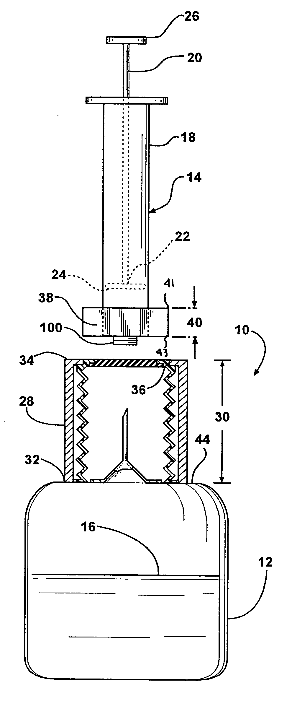
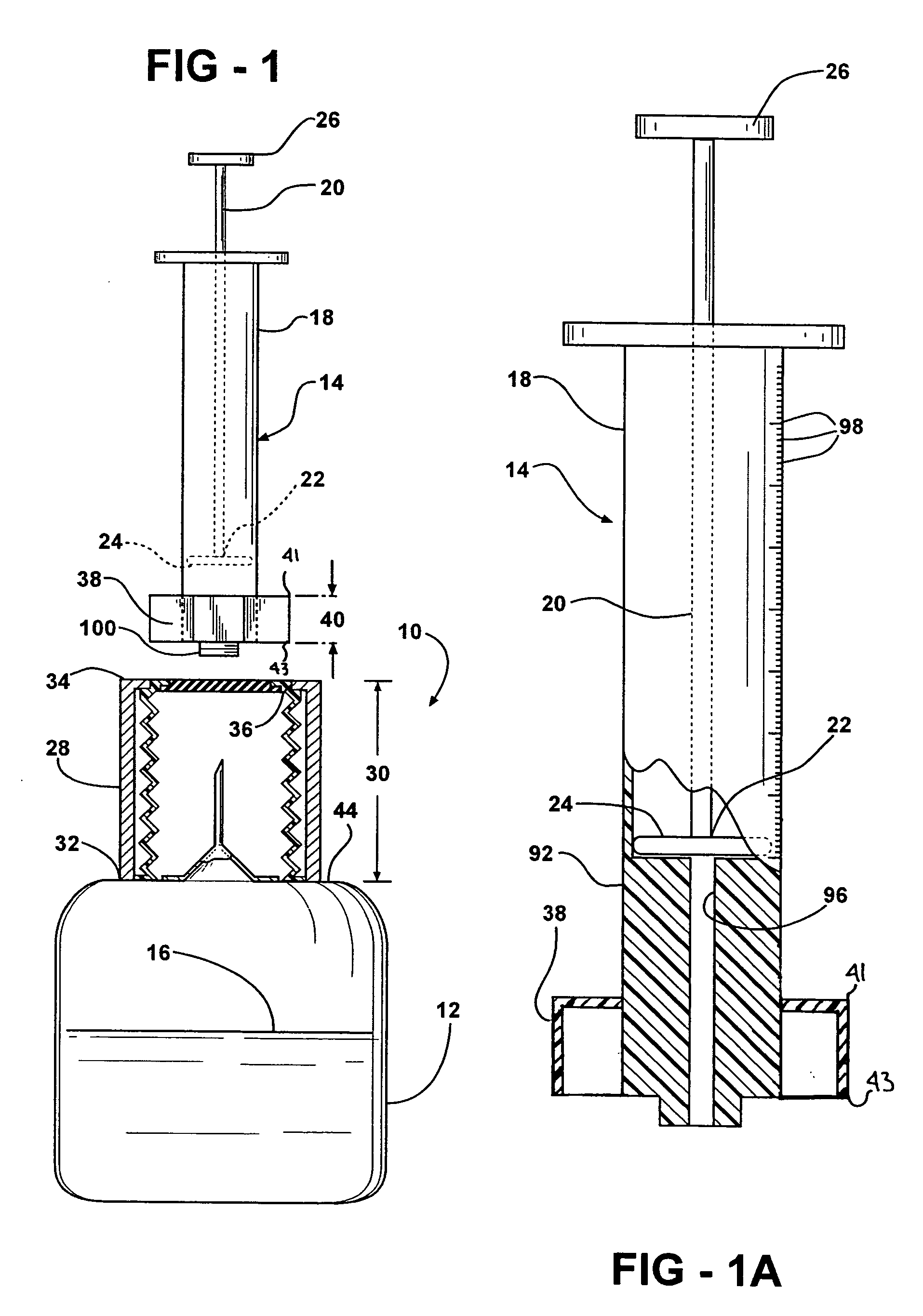
[0029] Additionally in this second embodiment, there is a seal, generally indicated at 48. The seal 48 includes an accordion sheath 50 and a rubber cap 52. Cilia 54 extend between an opening 56 and the barrel 18′ of the syringe 14′. The cilia 54 helps maintain the inner surface 36′ of the tube 28′ clear of any debris that might be associated with the entrance of the barrel 18′ into the tube 28′. The rubber cap 52 is pierceable by the needle 42 when the syringe 14′ is inserted into the tube 28′ and forced down over the needle 42. Once the syringe 14′ is inserted sufficiently within the tube 28′, the syringe 14′ and the bottle 12′ are inverted and the plunger 20 is retracted from the barrel 18 to pull the fluid 16 out of the bottle 12′ into the barrel 18′ of the syringe 14′, as is done with standard medication transfer from a bottle into a syringe.

[0030] Referring to FIG. 5, a perspective view of the second embodiment is shown. In this figure, a stop 58 extends around the needle 42 to...

third embodiment

[0031] Referring to FIGS. 7 through 9, the invention is generally shown at 10″, wherein double primed reference characters refer to similar elements as those in the first two embodiments. The fluid delivery assembly 10″ transfers fluid to a fluid receiving container, namely the syringe 14″. It should be appreciated that a device other than a syringe 14″ may be used with the fluid delivery assembly 10″. The fluid delivery assembly 10″ is fixedly secured to the fluid holding container, namely the first container 12″ or an extension of the first container 12″. The fluid holding container 12″ defines a reservoir 62 and a top surface 44″. The top surface 44″ covers the reservoir 62.

[0032] The tube 28″ extends out from the top surface to a neck opening 64. The tube 28″ defines an inner tube surface 36″ and defines the tube length 30″. The fluid delivery assembly 10″ includes a shape margin, generally shown at 66, which extends out of the lower edge 43″ of the mating yoke 38″. The shape ma...


PUM


Abstract

A fluid delivery assembly transfers fluid from a first fluid-filled container filled to a second fluid container. The fluid delivery assembly includes a tube extending through a tube length between a base end which is fixedly secured to one of the first and second fluid containers and a distal end. The tube has an inner surface defining a tube contour. The fluid delivery assembly also includes a mating yoke secured to the other containers. The mating yoke defines a body periphery correlating to the tube contour such that the mating yoke in the one fluid containers is received within the tube and is capable of moving along the tube length until the first and second fluid containers are in fluid communication. Another aspect of this invention is it incorporates a container which eliminates the need for an exposed needle to draw the medicine out of the container.

Description

BACKGROUND ART [0001] 1. Field of the Invention [0002] The invention relates to the delivery of fluids between storage containers. More particularly, the invention relates to a fluid delivery assembly for moving liquids between storage containers wherein the fluid delivery assembly is safe for the health care professional and the patient. [0003] 2. Description of the Related Art [0004] Advancements in medicine are responsible for the treatment of many illnesses that were once thought untreatable. Some of the treatments require the parenteral administration of fluids using a syringe or an IV. As these opportunities to successfully treat patients grows, so do the number of medicines and protocols required for these treatments. More treatments expose healthcare professionals to accidental needle sticks which may result in the infection of the healthcare professionals. This problem is compounded by having increased pressures to maximize the productivity of the facilities and increasing ...

Claims


Application Information

Patent Timeline
Patent Type & Authority Applications(United States)
IPC IPC(8): A61M5/32A61B19/00A61M5/00
CPCA61J1/2096A61J2001/2055A61J2001/201A61J1/201A61J1/2055
Inventor O'HARE, BRIDGET M.FARHAT, ALI Y.
Owner WIZARD MED
Learn More