
Electrophotographic photosensitive member, process cartridge and electrophotographic apparatus

a photosensitive member and electrophotography technology, applied in the direction of electrographic process apparatus, optics, instruments, etc., can solve the problems of high residual potential drawback in initial use and repeated use, and achieve the effects of improving the coating property of the photosensitive layer, improving the charging property, and improving the adhesion

Inactive Publication Date: 2006-10-19
CANON KK
View PDF11 Cites 13 Cited by
  • Summary
  • Abstract
  • Description
  • Claims
  • Application Information

AI Technical Summary

Benefits of technology

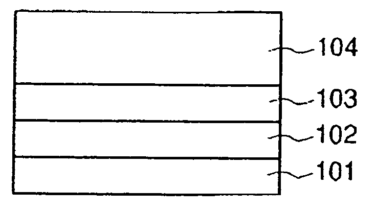
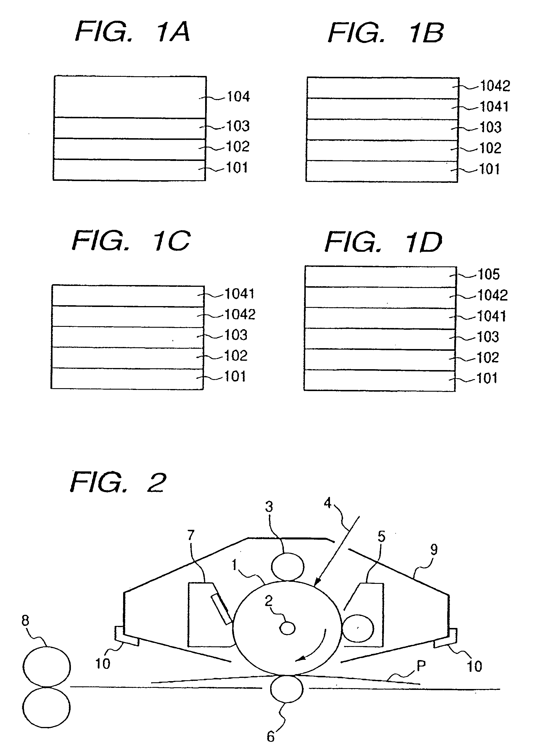
[0026] An object of the present invention is to provide an electrophotographic photosensitive member capable of suppressing a ghost phenomenon, even in a configuration having a conductive layer, an intermediate layer and a photosensitive layer in succession in this order on a substrate for covering a defect on the surface of the substrate, for improving a coating property of the photosensitive layer, for improving an adhesion between the substrate and the photosensitive layer, for protecting the photosensitive layer from an electrical destruction, for improving a charging property, and for improving a charge injecting property from the substrate to the photosensitive layer, by means of oxygen-deficient SnO2 excellent in a reuse property.
[0034] The present invention allows to provide an electrophotographic photosensitive member capable of suppressing a ghost phenomenon, even in a configuration having a conductive layer, an intermediate layer and a photosensitive layer in succession in this order on-a substrate for covering a defect on the surface of the substrate, for improving a coating property of the photosensitive layer, for improving an adhesion between the substrate and the photosensitive layer, for protecting the photosensitive layer from an electrical destruction, for improving a charging property, and for improving a charge injecting property from the substrate to the photosensitive layer, by means of oxygen-deficient SnO2 excellent in a reuse property.

Problems solved by technology

However, the aforementioned layer (i) of a high electrical resistance, when provided with a large film thickness, results in a drawback of a high residual potential in an initial state of-use and after repeated use.

Method used


Image

  • Electrophotographic photosensitive member, process cartridge and electrophotographic apparatus
  • Electrophotographic photosensitive member, process cartridge and electrophotographic apparatus
  • Electrophotographic photosensitive member, process cartridge and electrophotographic apparatus

Examples


example 1

[0111] An aluminum cylinder with a length of 260.5 mm and a diameter of 30 mm obtained by a hot extrusion in an environment of 23° C. and 60% RH (JIS-A3003, aluminum alloy ED tube, manufactured by Showa Aluminum Co.) was employed as a substrate The surface of the substrate had Rzjis of 0.8 μm.

[0112] In the present invention, the Rzjis was measured according to JIS-B0601 (1994), by employing a surface roughness meter SURFCORDER SE3500, manufactured by Kosaka Kenkyusho Co., under conditions of a feed rate of 0-1 mm / s, a cut-off λc of 0.8 mm and a measured length of 2.50 mm.

[0113] Then, 7.90 parts of TiO2 particles coated with oxygen-deficient SnO2 as conductive particles (powder resistivity: 80 Ωμcm, SnO2 covering rate (weight ratio): 50%), 3.30 parts of a phenolic binder resin (trade name: Plyophen J-325, manufactured by Dai-nippon Inks and Chemicals Inc., resin solid component: 60%), and 8.60 parts of methoxypropanol as a solvent were dispersed for 3 hours by using a sand mill uti...

example 2

[0139] An electrophotographic photosensitive member was prepared and evaluated in the same manner as in Example 1, except for following points. Obtained results are shown in Table 1.

[0140] In the conductive layer, an amount of the TiO2 particles coated with oxygen-deficient SnO2 as the conductive particles was changed to 7.63 parts, and an amount of the phenolic resin as the binder resin for the conductive layer was changed to 3.75 parts. As a result, the conductive layer had a surface roughness Rzjis of 1.7 μm and a volume resistivity of 8×10⁸ Ω·cm.

example 3

[0141] An electrophotographic photosensitive member was prepared arid evaluated in the same manner as in Example 1, except for following points. Obtained results are shown in Table 1.

[0142] In the conductive layer, an amount of the TiO2 particles coated with oxygen-deficient SnO2 as the conductive particles was changed to 7.73 parts, and an amount of the phenolic resin as the binder resin for the conductive layer was changed to 3.58 parts As a result, the conductive layer had a surface roughness Rzjis of 1.6 μm and a volume resistivity of 9×10⁷ Ω·cm


PUM

PropertyMeasurementUnit
volume resistivityaaaaaaaaaa
thicknessaaaaaaaaaa
thicknessaaaaaaaaaa

Abstract

The invention provides an electrophotographic photosensitive member including a conductive layer, an intermediate layer and a photosensitive layer in this order on a substrate, in which the conductive layer contains a binder resin and conductive particles, wherein the conductive particles are TiO2 particles coated with oxygen-deficient SnO2, the conductive particles have an average particle size of 0.2 to 0.6 μm and the conductive layer has a volume resistivity of 5×10⁵ to 8×10⁸Ω·cm. Also this invention provides a process cartridge and an electrophotographic apparatus equipped with such electrophotographic photosensitive member.

Description

BACKGROUND OF THE INVENTION [0001] 1. Field of the Invention [0002] The present invention relates to an electrophotographic photosensitive member, and a process cartridge and an electrophotographic apparatus including an electrophotographic photosensitive member. [0003] 2. Related Background Art [0004] Recently an electrophotographic photosensitive member utilizing an organic photoconductive material (organic electrophotographic photosensitive member) is being actively developed. [0005] An electrophotographic photosensitive member is basically constituted of a substrate, and a photosensitive layer formed on such substrate. In practice, however, various layers are often formed between the substrate and the photosensitive layer, for the purposes of covering a defect on the surface of the substrate, improving a coating property of the photosensitive layer, improving an adhesion between the substrate and the photosensitive layer, protecting the photosensitive layer from an electrical de...

Claims


Application Information

Patent Timeline
Patent Type & Authority Applications(United States)
IPC IPC(8): G03G5/14
CPCG03G5/104G03G5/10
Inventor MIKI, NOBUMICHINAGASAKA, HIDEAKISEKIYA, MICHIYOSEKIDO, KUNIHIKOMORIKAWA, YOSUKE
Owner CANON KK
Learn More