
Fuel cell using biofilms as catalyst for the cathode reaction an/or the anode reaction

a fuel cell and biofilm technology, applied in the field of fuel cell electrode treatment, can solve the problems of low efficiency, cell start-up difficulties, pollution problems inherent in the use of this type of catalyst, etc., and achieve the effect of improving the catalysis reaction

Inactive Publication Date: 2006-10-19
CENT NAT DE LA RECHERCHE SCI +1
View PDF6 Cites 29 Cited by
  • Summary
  • Abstract
  • Description
  • Claims
  • Application Information

AI Technical Summary

Benefits of technology

The present invention provides a process for improving the catalysis of a fuel cell electrode before the cell is operated. This is achieved by depositing a biofilm on the surface of the electrode and simultaneously subjecting it to a polarization potential. The process results in an electrode that is completely or partly covered by a biofilm that is capable of instantly catalyzing the electrode reaction when the cell is operated. The process can be carried out before or after the electrode is placed in the fuel cell device. The use of a biofilm to improve the catalysis of the electrodes eliminates the need for expensive mineral catalysts and makes the process more cost-effective. The process is also beneficial because it allows for the formation of a biofilm that is optimum for the specific fuel cell being operated.

Problems solved by technology

However, the use of such catalysts has the following drawbacks: they constitute products that are both expensive, because of the amounts needed to obtain satisfactory catalysis, and potential pollutants of the environment; and they have a low efficiency at low temperatures, such as room temperature, which may lead to cell start-up difficulties.
However, the pollution problem inherent in the use of this type of catalyst still remains.
However, the performance of such cells remains insufficient.
In addition, the use of microorganisms in the abovementioned fuel cells does not contribute to the improvement in the electrochemical rates at the electrodes, but to the biological production of fuel or to the regeneration of a mediator compound.
However, although these studies are aimed at improving the rates at the electrodes, and particularly at the cathode, they make use of relatively expensive enzymes and sometimes of additional organic compounds that act as electrochemical mediators to ensure electron transfer between the active site of the enzyme and the electrode.
These studies have demonstrated that the growth of biofilms leads to an increase in the corrosion potential of these materials, due to an increase in the cathode reaction rate of the corrosion phenomenon.
However, the role of biofilms in improving the operating performance of a battery, especially in the Hasvold publication “Sea-water battery for subsea control systems”, Journal of Power Sources, 65, pages 253-261, 1997 [5], mentioned above, is dealt with as a contingent phenomenon taking place during operation of the battery, or even as a phenomenon hampering proper operation of the battery, when the biofilm assumes excessively large proportions and consequently impedes the accessibility of the reactants at the cathode.
Furthermore, that document does not present specific techniques for promoting and optimizing the growth of the biofilm so as to improve the performance of the battery.
There is therefore at the present time a real need for improving the catalysis of electrode reactions, especially the cathode reaction, which situation constitutes a limitation for the proper operation of a fuel cell.

Method used

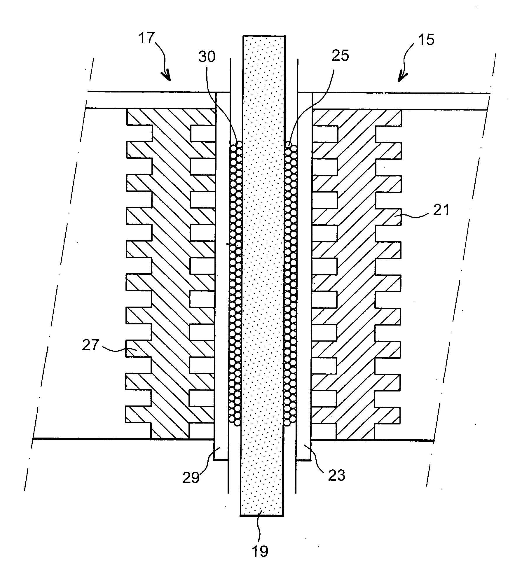
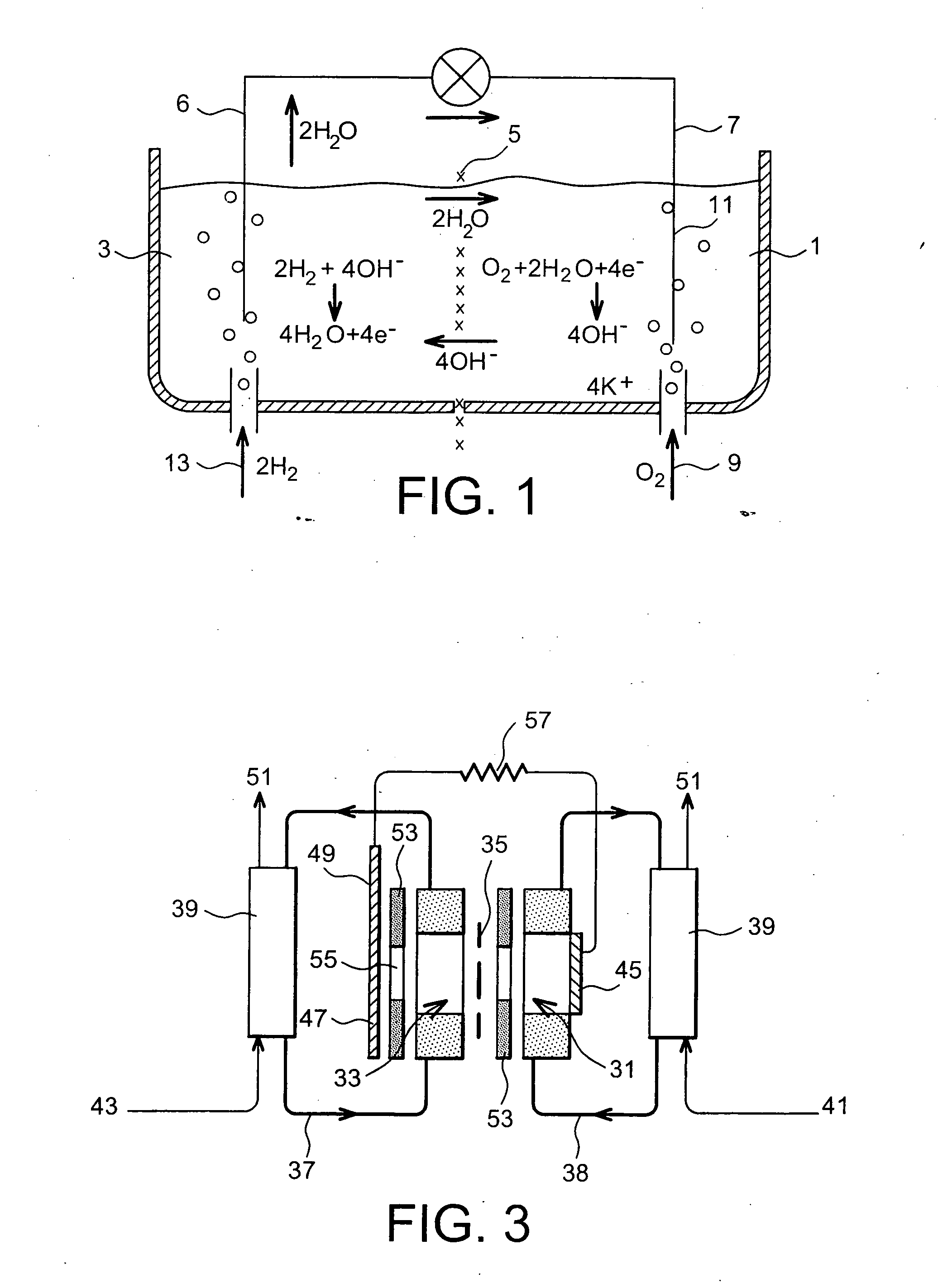
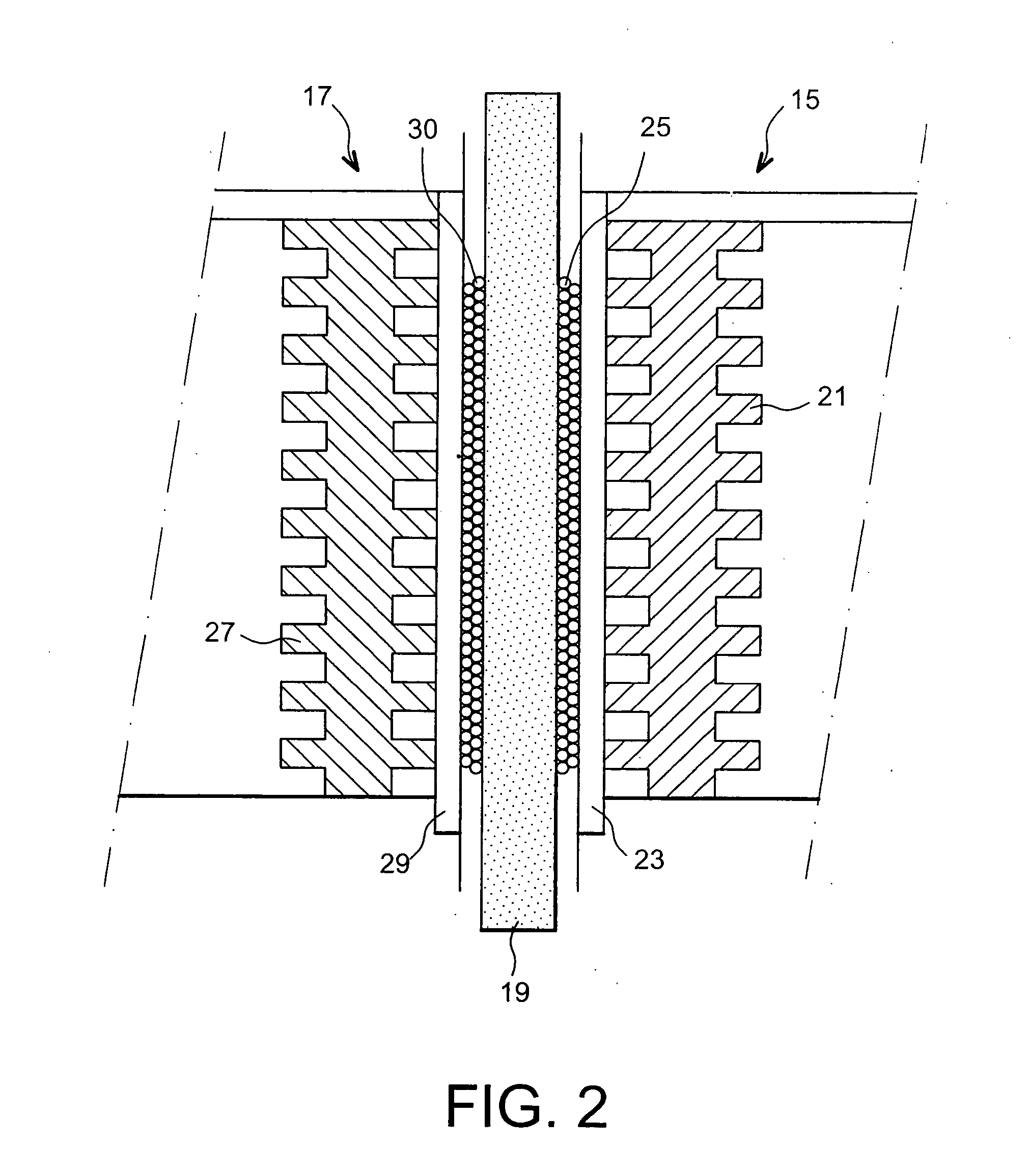

Image

  • Fuel cell using biofilms as catalyst for the cathode reaction an/or the anode reaction
  • Fuel cell using biofilms as catalyst for the cathode reaction an/or the anode reaction
  • Fuel cell using biofilms as catalyst for the cathode reaction an/or the anode reaction

Examples


example 2

[0093] The characteristics of the first series of tests were the following: [0094] polarization potential: −0.10 V / SCE; [0095] polarization time: 15 days; [0096] fluid circulating on the cathode side: seawater; [0097] fluid circulating on the anode side: distilled water+NaOH (pH=12.5); [0098] working area of the cathode: 9 cm2.

[0099] The current values recorded as a function of time were identical to those shown in Example 1.

[0100] In this first series of tests, the power delivered by the cell was measured for various electrical resistance values.

[0101] In a second series of tests, the power delivered by the cell was measured for various electrical resistance values, the cell not having a biofilm on the cathode and not having undergone the conditioning step.

[0102] The (power with biofilm / power without biofilm) ratios are given in Table 3 below.

TABLE 3Resistance (in Ω)1101001000104105106Ratio868181103—24—

example 3

[0103] The characteristics of the first series of tests were the following: [0104] polarization potential: −0.30 V / SCE; [0105] polarization time: 17 days; [0106] fluid circulating on the cathode side: seawater; [0107] fluid circulating on the anode side: distilled water+NaOH (pH base=12.5); [0108] working area of the cathode: 1.8 cm2.

[0109] In this first series of tests, the power delivered by the cell was measured for various electrical resistance values.

[0110] In a second series of tests, the power delivered by the cell was measured for various electrical resistance values, the cell not having a biofilm on the cathode and not having undergone the conditioning step.

[0111] The (power with biofilm / power without biofilm) ratios is are given in Table 4 below.

TABLE 4Resistance (in Ω)1101001000104105106Ratio798584511054

[0112] It may be seen that, for the three examples, the presence of a biofilm deposited on at least part of the surface of the cathode before it is placed in the cell...


PUM

PropertyMeasurementUnit
timeaaaaaaaaaa
temperaturesaaaaaaaaaa
temperatureaaaaaaaaaa

Abstract

The present invention relates to a process for the treatment of at least one of the electrodes (cathode and / or anode) of a fuel cell, before the said cell is operated, and before or after the said electrode is placed in the said cell, comprising the step consisting in forming a biofilm on at least part of the surface of the said electrode, by immersing the said electrode in a medium capable of causing the growth of biofilms, the said biofilm being intended to catalyse the reaction at the electrode, and the step consisting simultaneously in subjecting the said electrode to a polarization potential. The invention also relates to a fuel cell comprising at least one electrode covered with a biofilm, obtained before the said electrode is placed in the cell, and to the electrode.

Description

TECHNICAL FIELD [0001] The present invention relates to a process for the treatment of a fuel cell electrode (cathode and / or anode), the said treatment being intended to improve the catalysis of the reaction at the electrode, and to a fuel cell provided with a biofilm on at least part of the surface of the said electrode. [0002] The general field of the invention is therefore that of fuel cells and more particularly that of the catalysis of the reactions at the electrodes of fuel cells. PRIOR ART [0003] The basic principle covering the operation of a fuel cell, for example a hydrogen / air fuel cell, is the electrochemical combustion of dihydrogen (H2) and dioxygen (O2). [0004] The reactions at the terminals of the electrodes are represented by the following equations (1) and (2): [0005] (1) at the anode:H2→2H++2e− or H2+2OH−→2H2O +2e−; [0006] (2) at the cathode:½O2+2H++2e−→H2O or ½O2+H2O+2e−→2OH−. [0007] These two reactions have slow rates, resulting in catalysts being placed at the ...

Claims


Application Information

Patent Timeline
Patent Type & Authority Applications(United States)
IPC IPC(8): H01M4/90B05D5/12H01M4/88H01M4/86H01M8/16
CPCH01M4/8892Y02E60/527H01M8/16H01M4/90Y02E60/50
Inventor BERGEL, ALAIN
Owner CENT NAT DE LA RECHERCHE SCI
Learn More