
Fine-grained forward-secure signature scheme

Inactive Publication Date: 2006-10-19
IBM CORP
View PDF9 Cites 14 Cited by
  • Summary
  • Abstract
  • Description
  • Claims
  • Application Information

AI Technical Summary

Benefits of technology

[0008] In accordance with a first aspect of the present invention, there is given a method for providing a secret cryptographic key sk and a public cryptographic key pk applicable in a network of connected computer nodes using a signature scheme. The method is executable by a first computer node and comprises the steps of generating the secret cryptographic key sk by selecting two random factor values P, Q, multiplying the two selected random factor values P, Q to obtain a modulus value (N), and selecting a secret base value g′, h′, x′ in dependence on the modulus value N, wherein the secret base value g′, h′, x′ forms part of the secret cryptographic key g′, h′, x′. The method further comprises generating the public cryptographic key pk by selecting a number I of exponent values e1, . . . , eI, and deriving a public base value g, h, x from the exponent values e1, . . . , eI and the secret base value g′, h′, x′ wherein the public base value g, h, x and the modulus value N form part of the public cryptographic key g, h, x, N. The method further comprises the steps of deleting the two random factor values P, Q; and providing the public cryptographic key g, h, x, N within the network; such that the public cryptographic key g, h, x, N and at least one of the selected exponent values e1, . . . , eI is usable for verifying a signature value i, y, a on a message m to be sent within the network to a second computer node for verification.
[0009] In a second aspect of the present invention, there is given a method for providing a signature value i, y, a on a message m in a network of connected computer nodes, the method being executable by a first computer node and comprising the steps of selecting a first signature element a; selecting a signature exponent value ei from a number I of exponent values e1, . . . , eI; and deriving a second signature element y from a provided secret cryptographic key g′i, h′1, x′i, the message m, and the number I of exponent values e1, . . . , eI such that the first signature element a, the second signature element y, and the signature exponent value ei satisfy a known relationship with the message m and a provided public cryptographic key g, h, x, N, wherein the signature value i, y, a comprises the first signature element a, the second signature element y, and a signature reference i to the signature exponent value ei, the signature value i, y, a being sendable within the network to a second computer node for verification.
[0010] In a third aspect of the present invention, there is given a method for verifying a signature value i, y, a on a message m in a network of connected computer nodes, the method being executable by a second computer node and comprising the steps of receiving the signature value i, y, a from a first computer node; deriving a signature exponent value ei from the signature value i, y, a; and verifying wh

Problems solved by technology

Ordinary digital signature schemes suffer from a fundamental shortcoming: once the secret key is leaked, for example because a hacker managed to break into the signer's computer, and, when this leakage is detected, the public key is revoked then all signatures produced by the signer become reputable, i.e., it is no longer possible to distinguish whether a signature was produced by the signer or the hacker.
Therefore ordinary signature schemes can pre se not provide non-repudiation.
However, this solution requires frequent interaction with a trusted third party, e.g., the time-stamping service, which is not desirable.
However, the scheme is rather inefficient in terms of (public and secret) storage.
However, current forward secure signature schemes suffer from the following problem.

Method used


Image

  • Fine-grained forward-secure signature scheme
  • Fine-grained forward-secure signature scheme
  • Fine-grained forward-secure signature scheme

Examples


Embodiment Construction

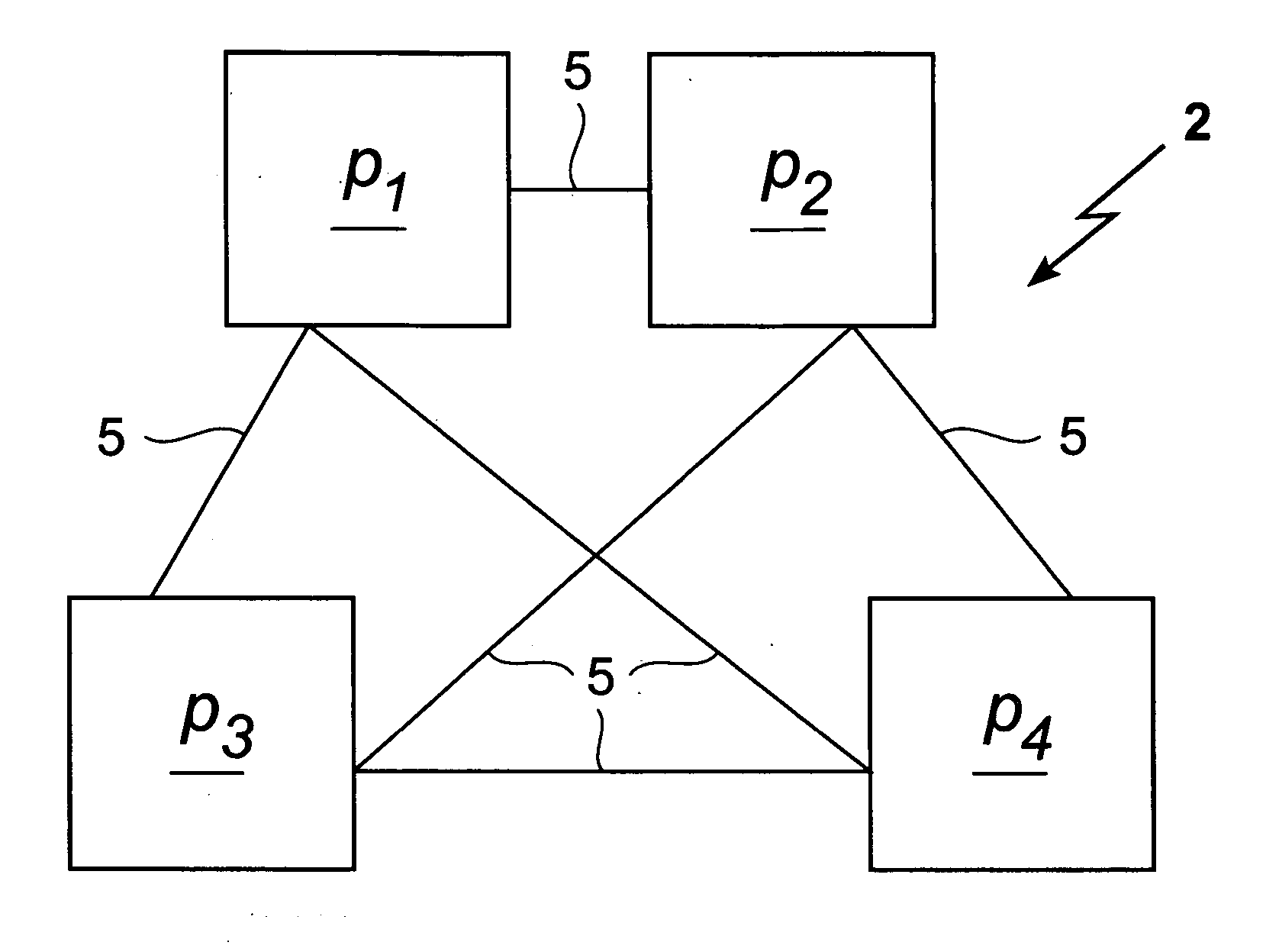
[0055] With general reference to the figures, the features of a fine-grained forward-secure signature schemes within a network are described in more detail below.

[0056] Turning to FIG. 1 which shows an example of a common computer system 2. It comprises here a first, second, third, and fourth computer node p1, p2, p3, p4 which are connected via communication lines 5 to a network. Each computer node p1, p2, p3, p4, may be any type of computer device or network device known in the art from a computer on a chip or a wearable computer to a large computer system. The communication lines can be any communication means commonly known to transmit data or messages from one computer node to another. For instance, the communication lines may be either single, bi-directional communication lines 5 between each pair of computer nodes p1, p2, p3, p4 or one unidirectional line in each direction between each pair of computer nodes p1, p2, p3, p4. The common computer system 2 is shown to facilitate ...


PUM


Abstract

The presented methods form the basis of a forward-secure signature scheme that is provably secure. Moreover, the presented methods form also the basis of a fine-grained forward-secure signature scheme that is secure and efficient. The scheme allows to react immediately on hacker break-ins such that signatures from the past still remain valid without re-issuing them and future signature values based on an exposed key can be identified accordingly. In general, each prepared signature carries an ascending index such that once an index is used, no lower index can be used to sign. Then, whenever an adversary breaks in, an honest signer can just announce the current index, e.g., by signing some special message with respect to the current index, as part of the revocation message for the current time period. It is then understood that all signatures made in prior time periods as well as all signatures make in the revoked period up to the announced index are valid, i.e., non-reputable.

Description

TECHNICAL FIELD [0001] The present invention relates to a method for providing a secret cryptographic key and public cryptographic key applicable in a network of connected computer nodes using a signature scheme. Moreover, the invention relates to methods for providing and verifying a signature value on a message in the network of connected computer nodes. A method for communicating the validity of the generated signature value in the event of a detected intrusion is also disclosed herein. BACKGROUND OF THE INVENTION [0002] Electronic or digital signatures are used to authenticate information, that is to securely tie the contents of an electronic document to a signer, more precisely, to the signer's public key. Only the true signer should be able to produce valid signatures, and anyone should be able to verify them in order to convince oneself that the signer indeed signed the document. While many digital signature schemes have been proposed so far, a few are used in practice today....

Claims


Application Information

Patent Timeline
IPC IPC(8): H04L9/00G09C1/00H04L9/32
CPCH04L9/3255H04L9/14H04L9/32H04L9/08
Inventor CAMENISCH, JAN
Owner IBM CORP
Learn More