
Four-wheel drive vehicle running normally and with object towed thereby

a four-wheel drive, normal technology, applied in the direction of brake systems, process and machine control, instruments, etc., can solve the problems of affecting the durability of differentials, changing the diameter of front and rear wheels, and increasing the size of peripheral parts of driving wheels, so as to avoid an increase in the size of peripheral parts

Inactive Publication Date: 2006-10-19
TOYOTA JIDOSHA KK
View PDF5 Cites 25 Cited by
  • Summary
  • Abstract
  • Description
  • Claims
  • Application Information

AI Technical Summary

Benefits of technology

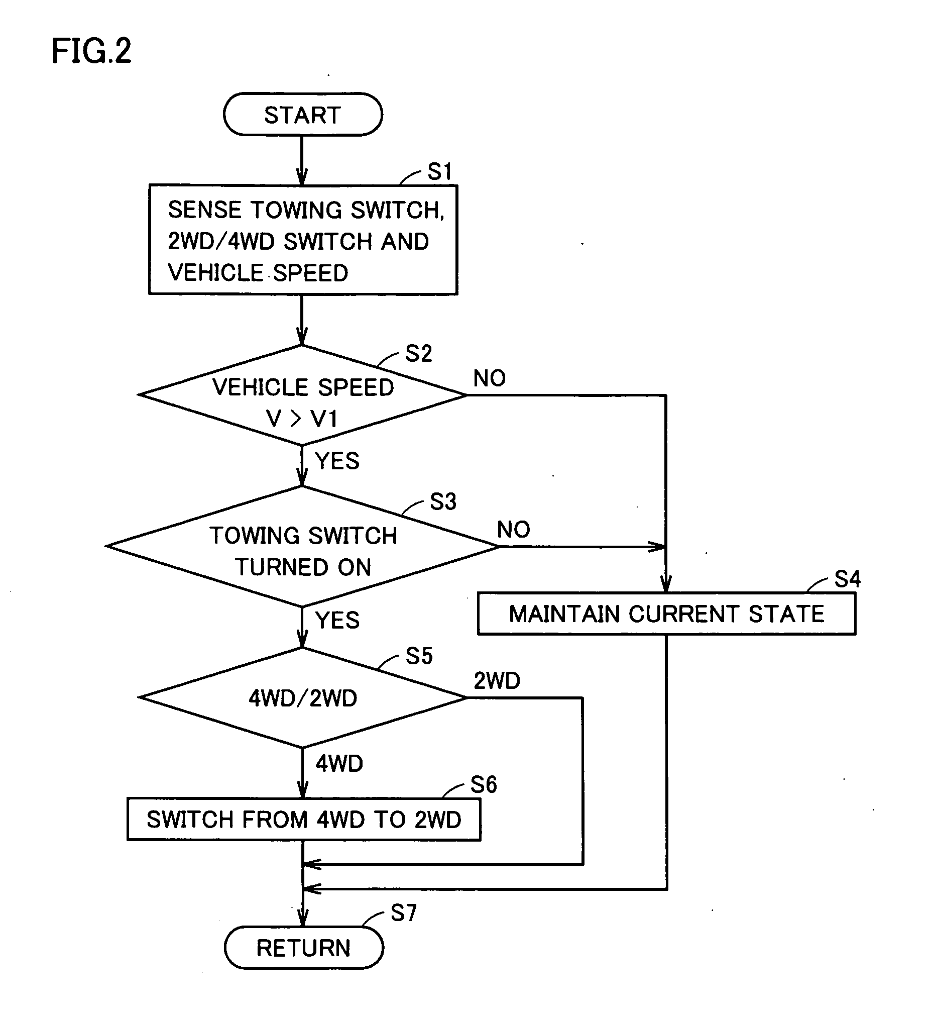
The present invention is a four-wheel drive vehicle that can run with an object towed by it while avoiding an increase in the size of the driving wheels. The vehicle includes a speed detecting portion, an input portion, a switching portion, and a control portion. The control portion can switch between a two-wheel driving state and a four-wheel driving state, but will switch to the two-wheel driving state if the vehicle tows a trailer and runs in the four-wheel driving state when the vehicle speed exceeds a predetermined value. The vehicle can also have a switch operated by the driver to designate a towing mode. The control portion detects that the vehicle tows a trailer based on the vehicle speed, gradient, and acceleration. The vehicle can also have a pressure sensing portion and an acceleration sensing portion to detect if the vehicle tows a trailer. The control portion maintains the driving state determined in accordance with the input portion if the vehicle speed is less than a predetermined value. The vehicle includes a mechanical power source and a switch unit to transfer torque generated by the power source to either the rear propeller shaft or the front propeller shaft in the two-wheel drive state, and to both in the four-wheel drive state. The vehicle can also have a transmission to transfer the torque received from the engine to the switch unit. The foregoing and other objects, features, aspects, and advantages of the present invention will become more apparent from the following detailed description of the invention.

Problems solved by technology

This may lead to an increase in size of peripheral parts of the driving wheels.
This may cause a change in diameters between the front tires and the rear tires to lead a full-time differential of the center differential.
As a result, durability of the differential may be impaired, and there is a need to solve these problems in towing by a four-wheel drive vehicle.

Method used


Image

  • Four-wheel drive vehicle running normally and with object towed thereby
  • Four-wheel drive vehicle running normally and with object towed thereby
  • Four-wheel drive vehicle running normally and with object towed thereby

Examples


first embodiment

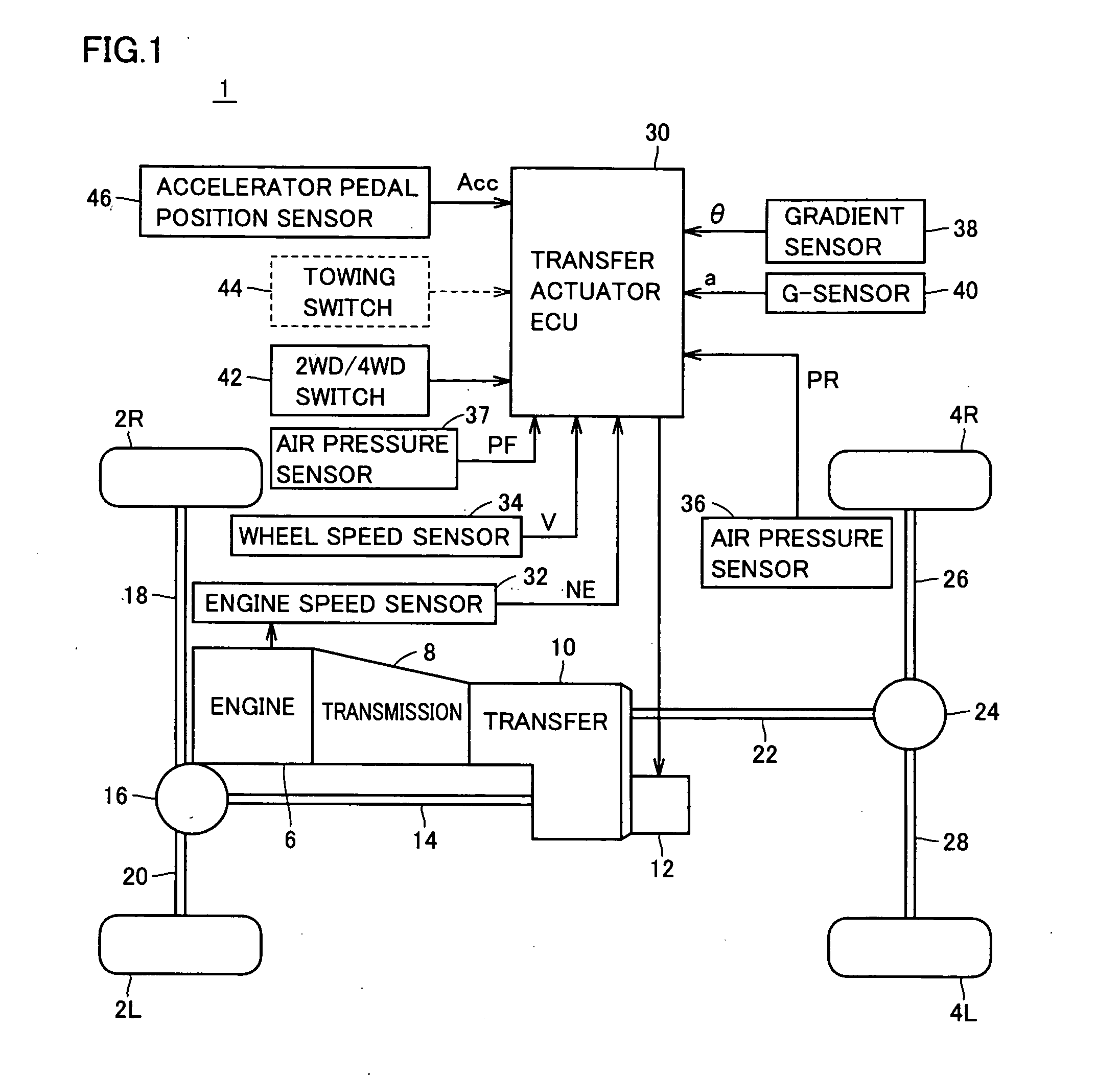
[0030]FIG. 1 is a block diagram showing a configuration of a vehicle 1 according to an embodiment of the present invention.

[0031] Referring to FIG. 1, vehicle 1 includes front wheels 2L, 2R, rear wheels 4L, 4R, an engine 6, a transmission 8 and a transfer 10.

[0032] Transfer 10 is a part for getting a torque which is transmitted from a powertrain in a base driving mode (a rear wheel drive in FIG. 1) to the wheels which are not originally driving wheels. Vehicle 1 further includes a transfer actuator 12, a front propeller shaft 14, a front differential 16 and front drive shafts 18, 20.

[0033] Vehicle 1 further includes a rear propeller shaft 22, a rear differential 24 and rear drive shafts 26, 28.

[0034] Transfer 10 has a center differential incorporated therein. Transfer actuator 12 is, for example, an electric motor. In response to the rotation of the motor, a shift fork moves to cause a movement of a sleeve got caught in the shift fork and thereby to switch back and forth between...

second embodiment

[0053]FIG. 3 is a flowchart showing a control structure of a program of transfer actuator ECU 30 carried out by a second embodiment.

[0054] Referring to FIGS. 1 and 3, first in step S11, a transfer actuator ECU 30 senses a gradient θ, an acceleration α, a setting of a 2WD / 4WD switch 42, a vehicle speed V, an engine speed NE and an accelerator pedal position ACC. In step S12, transfer actuator ECU 30 then determines whether vehicle speed V is greater than a predetermined value V1 or not.

[0055] If vehicle speed V is greater than V1, the process proceeds to step S13, and if not, the process proceeds to step S15.

[0056] In step S13, transfer actuator ECU 30 determines whether gradient θ of the vehicle sensed by a gradient sensor 38 is greater than a predetermined value θ1 or not.

[0057] In transfer actuator ECU 30, a table or map representing a relationship between an engine throttle angle and a vehicle speed (and a driving acceleration), and a gradient of the road surface on which the...

third embodiment

[0072]FIG. 5 is a flowchart showing a control structure of a program of a transfer actuator ECU 30 carried out in a third embodiment.

[0073] Referring to FIGS. 1 and 5, first in step S21, transfer actuator ECU 30 senses air pressures in a front wheel and a rear wheel, an acceleration α, a setting of a 2WD / 4WD switch 42, a vehicle speed V, an engine speed NE, and an accelerator pedal position ACC. In step S22, transfer actuator ECU 30 then determines whether vehicle speed V is greater than a predetermined value V1 or not.

[0074] If vehicle speed V is greater than V1, the process proceeds to step S23, and if not, the process proceeds to step S25.

[0075] In step S23, transfer actuator ECU 30 determines whether or not the air pressure in the rear wheel is greater than the air pressure in the front wheel. As shown in FIG. 6, the air pressure in the rear wheel is greater than the air pressure in the front wheel in towing an object. This suggests that the vehicle is in the towing state.

[0...


PUM


Abstract

A vehicle includes a wheel speed sensor sensing a vehicle speed V, a 2WD / 4WD switch operative to input an instruction to switch between a two-wheel driving state and a four-wheel driving state, a transfer and an actuator switching the two-wheel driving state and the four-wheel driving state, and an ECU driving the actuator. The ECU instructs the actuator to switch from the four-wheel driving state to the two-wheel driving state regardless of the switching instruction from the 2WD / 4WD switch if the vehicle tows a trailer and runs in the four-wheel driving state when the vehicle speed exceeds a predetermined value. Consequently, it is possible to provide a four-wheel drive vehicle capable of running while towing an object and also avoiding an increase in the size of the peripheral parts of driving wheels.

Description

[0001] This nonprovisional application is based on Japanese Patent Application No. 2005-116655 filed with the Japan Patent Office on Apr. 14, 2005, the entire contents of which are hereby incorporated by reference. BACKGROUND OF THE INVENTION [0002] 1. Field of the Invention [0003] The present invention relates to a four-wheel drive vehicle, and particularly to a four-wheel drive vehicle running both normally and with an object towed thereby. [0004] 2. Description of the Background Art [0005] One of the purposes of the use of vehicles such as a SUV (sport utility vehicle) and a pickup truck is to run towing a trailer, a camping car or a cart loading a boat thereon which is coupled to the back of the vehicle. [0006] Japanese Patent Laying-Open No. 2003-014100 discloses a technology aiming to increase durability of a transmission by engaging a lock-up clutch in a varied amount when it is determined that a vehicle tows a trailer and so on. [0007]FIG. 6 is a diagram for illustrating a r...

Claims


Application Information

Patent Timeline
Patent Type & Authority Applications(United States)
IPC IPC(8): B60K17/34
CPCB60K23/08B60Y2200/147B60W2520/10
Inventor HOMAN, AKINORIMUNAKATA, SATOSHIAOYAMA, YOSHIYUKINOGUCHI, KAZUTAKA
Owner TOYOTA JIDOSHA KK
Learn More