Method for manufacturing an optical fiber preform by mcvd

Inactive Publication Date: 2006-10-19
LG CABLE LTD (KR)
View PDF11 Cites 11 Cited by
  • Summary
  • Abstract
  • Description
  • Claims
  • Application Information

AI Technical Summary

Benefits of technology

[0017] The present invention is designed on the consideration of the above problems. Therefore, an object of the present invention is to provide a method for manufacturing an optical fiber preform which is capable of minimizing or eliminating an index dip phenomenon existing at the center of the preform core.
[0018] In order to accomplish the above object, the present invention provides a method for manufacturing an optical fiber preform by MCVD, which includes an etching / collapsing process simultaneously performing an etching process for injecting a reaction gas into a tube and a collapsing process for collapsing the tube by applying heating just before a closing process for lastly collapsing the quartz tube and making in the shape of quartz rod in order to minimize or eliminate an index dip existing at the center of the preform core.
[0020] According to the present invention, it is possible to minimize or eliminate an index dip phenomenon by improving refractive index of the optical fiber preform. By using the optical fiber preform of the present invention, it is possible to make an optical fiber having improved a bandwidth and optical characteristics, especially, to make a multi-mode optical fiber for giga-bit Ethernet.
[0021] A multi-mode optical fiber for gigabits Ethernet is optimized to a system utilizing a light source of laser by eliminating an index dip existing at the center of the prior multi-mode optical fiber core, and finely controlling a refractive index profile. For optical transmission of several gigabits data rate, differently as LED (Light Emitting Diode) used in the prior optical fiber, a light source such as FP-LD (Fabry-Perot Laser Diode) or VDSEL (Vertical Cavity Surface Emitting Laser) having small beam spot size is used. Thus, for use of such light source, there is required to finely control the refractive index profile and improve a Restricted Mode Launching Bandwidth.

Problems solved by technology

The index dip, the index peak and resultant irregularity of the refractive index may deteriorate the microbending loss and PMD (Polarization Mode Dispersion) of the single mode fiber due to the increase of the potential stress caused by asymmetry of the refractive index and may significantly decrease a bandwidth and a differential mode play in the multimode.
However, volatilization of GeO2 due to a high temperature may also occur in the closing process.
Despite minimizing the inner diameter of the quartz tube after the collapsing process 200 however, the inner diameter is increased again during the etching process 300, so there are still limitations in minimizing or preventing volatilization of GeO2 in the closing process.
However, this patent fails to disclose a method for optimizing the inner diameter of the tube by simultaneously performing etching and collapsing before the closing process in order to minimize additional volatilization of GeO2 generated in the closing process due to increase of the inner diameter of the tube during the etching process.

Method used


Image

  • Method for manufacturing an optical fiber preform by mcvd
  • Method for manufacturing an optical fiber preform by mcvd
  • Method for manufacturing an optical fiber preform by mcvd

Examples


Embodiment Construction

[0035] Hereinafter, preferred embodiments of the present invention will be described in detail with reference to the accompanying drawings.

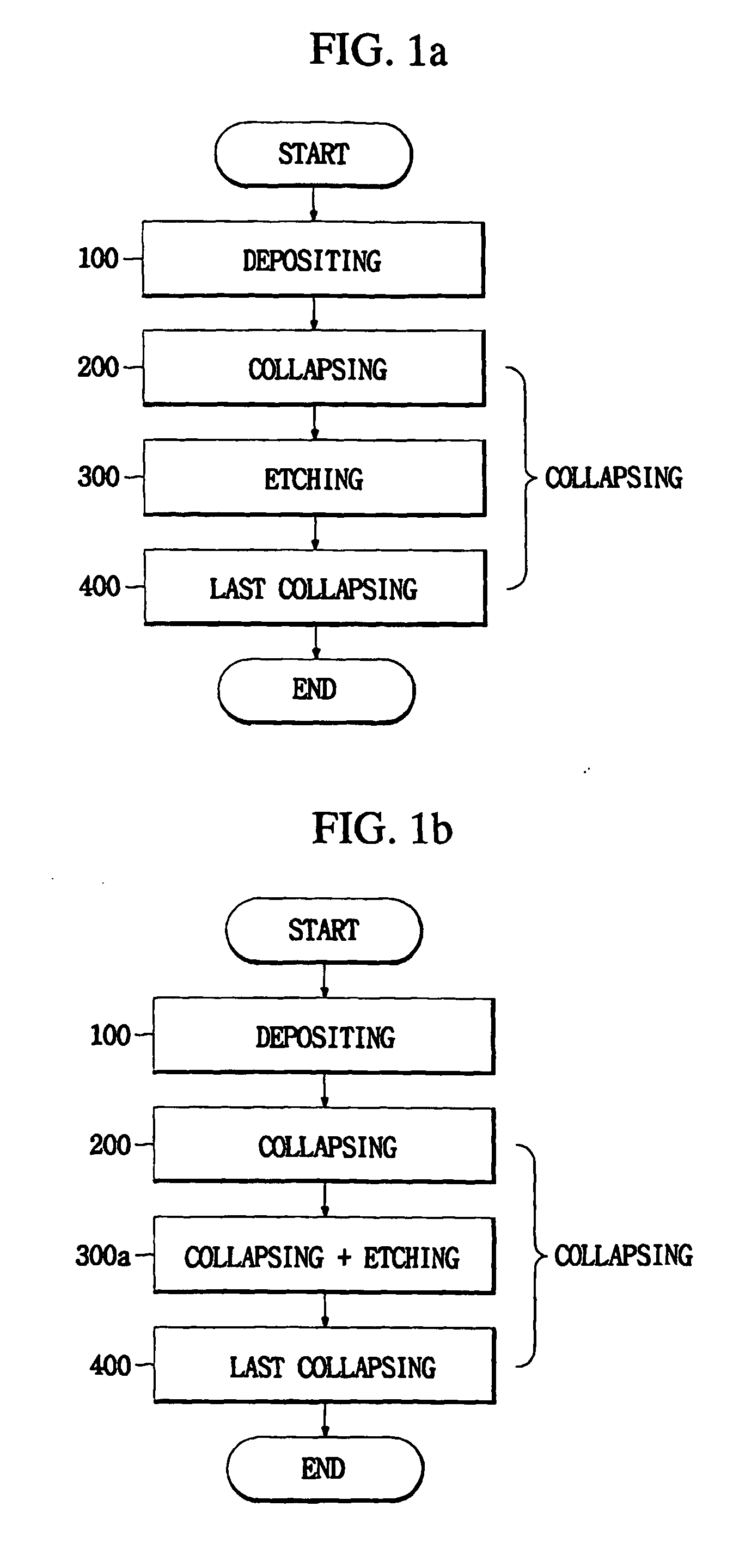
[0036] First, FIG. 1b is a flowchart for illustrating a method for fabricating an optical fiber preform by MCVD (Modified Chemical Vapor Deposition) according to the present invention.

[0037] Referring to FIG. 1b, the method for fabricating an optical fiber preform according to the present invention includes a depositing process 100, a collapsing process 200, an etching / collapsing process 300a, and a closing process 400.

[0038] Hereinafter, the method for fabricating an optical fiber preform according to the present invention is described process by process with reference to the accompanying drawings.

1. Depositing Process (see FIG. 2)

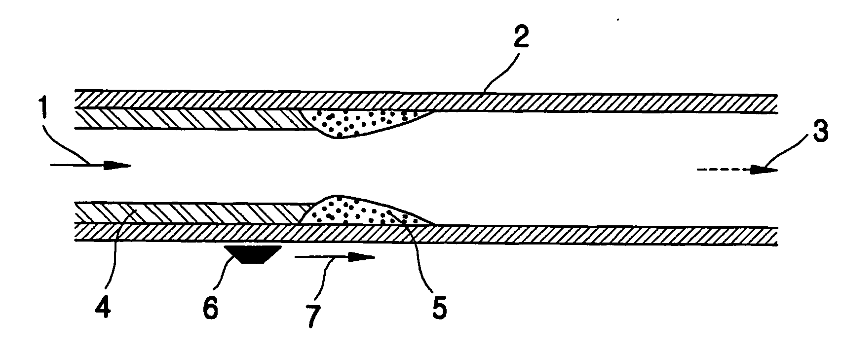
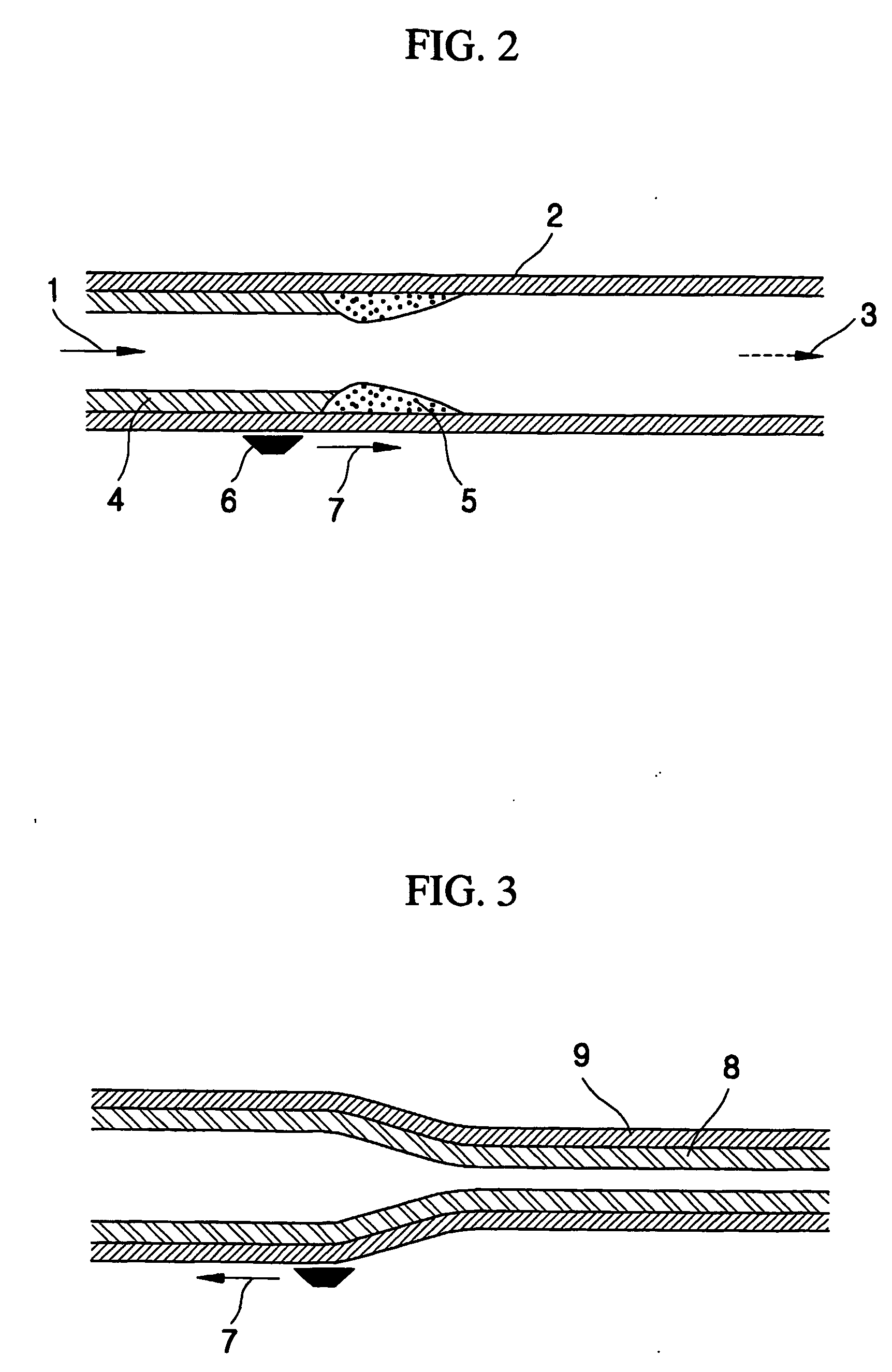
[0039] As shown in FIG. 2, in the depositing process, a reaction gas 1 such as SiCl4, GeCl4, POCl3, He and O2 is injected into a quartz tube 2. Then, the outside of the quartz tube 2 is heated by a torch 6 slowly...


PUM

PropertyMeasurementUnit
Flow rateaaaaaaaaaa
Diameteraaaaaaaaaa
Speedaaaaaaaaaa

Abstract

Disclosed is a method for manufacturing an optical fiber preform in MCVD, which simultaneously performs an etching process for injecting a reaction gas for etching into a tube and a collapsing process for heating and collapsing the tube in order to minimize or eliminate an index dip existing at the center of the preform core. By using this method, the index dip phenomenon of the optical fiber preform can be minimized or eliminated, so it is possible to make an optical fiber having improved optical characteristics, particularly having improvement in a bandwidth and a polarization mode dispersion (PMD).

Description

TECHNICAL FIELD [0001] The present invention relates to a method for manufacturing an optical fiber preform by Modified Chemical Vapor Deposition (MCVD), and more particularly to a method for manufacturing an optical fiber having improved optical characteristics by eliminating an index dip generated during processing. Especially, by using this method, it is possible to manufacture a multi-mode optical fiber capable of several gigabit transmissions without other subsidiary materials. BACKGROUND ART [0002]FIG. 1a is a flowchart showing a method for making an optical fiber preform according to a conventional MCVD. [0003] In general, an optical fiber preform is manufactured through a depositing process 100 and a collapsing process 200 to 400. The collapsing process more particularly includes a collapsing process 200, an etching process 300, and a closing process 400. [0004] A method for making an optical fiber preform is classified into an outside deposition manner and an inside deposit...

Claims


Application Information

Patent Timeline
IPC IPC(8): C03B37/018
CPCC03B37/01861C03B2203/26C03B2201/31C03B37/01869
Inventor HONG, CHOON-KEUNKANG, BYUNG-YOONLEE, DONG-WOOKKANG, BYUNG-CHUL
Owner LG CABLE LTD (KR)
Why Eureka
Try Eureka