
9-Aryl and bisayl substituted polyfluorenes

a polyfluorene and bisayl technology, applied in the field of semiconductive polymers, can solve the problems of less electrochemical stability of materials containing these lower electron affinities, short lifetime of materials, and increased sensitivity to degradation, so as to improve the electron affinity of known polyfluorenes, improve pled performance, and improve the effect of electron injection

Active Publication Date: 2006-10-12
CAMBRIDGE DISPLAY TECH LTD
View PDF6 Cites 12 Cited by
  • Summary
  • Abstract
  • Description
  • Claims
  • Application Information

AI Technical Summary

Benefits of technology

[0020] The present inventors have determined that improved electron Injection, and therefore improved PLED performance, may be accomplished by increasing the electron affinity of known polyfluorenes.
[0033] Preferred electron withdrawing heteroaryls according to (b) are optionally substituted N-containing heteroaryls, in particular optionally substituted pyridines, most particularly pyridine-4-yl; pyrazines; pyrimidines; pyridazines; triazines, most particularly 1,3,5-triazine-2-yl and oxadiazoles. The electron withdrawing heteroaryl may be substituted with electron withdrawing groups as outlined above to further increase its electron withdrawing effect.
[0050] The inventors have found that polymers according to the invention function effectively as electron transporting materials for red, green or blue electroluminescent polymers without adversely affecting device properties as has been found for systems having aliphatic electron withdrawing 9-substituents such as perfluoroalkyl.

Problems solved by technology

A difficulty encountered with blue electroluminescent polymers is that their lifetime (i.e. the time taken for brightness to halve from a given starting brightness at fixed current) tends to be shorter than that of corresponding red or green materials.
It is therefore possible that materials comprising these lower electron affinities are less electrochemically stable and therefore more prone to degradation.
This results in the further problem that the energy gap between the LUMO and the workfunction of the cathode for a typical blue electroluminescent polymer is greater than that for a typical red or green electroluminescent polymer.
This may contribute to lower efficiency.
This limitation is particularly restrictive in the case of blue electroluminescent polymers since the bandgap required for blue emission is the largest of red, green and blue.

Method used


Image

  • 9-Aryl and bisayl substituted polyfluorenes
  • 9-Aryl and bisayl substituted polyfluorenes
  • 9-Aryl and bisayl substituted polyfluorenes

Examples


examples

Monomer Examples

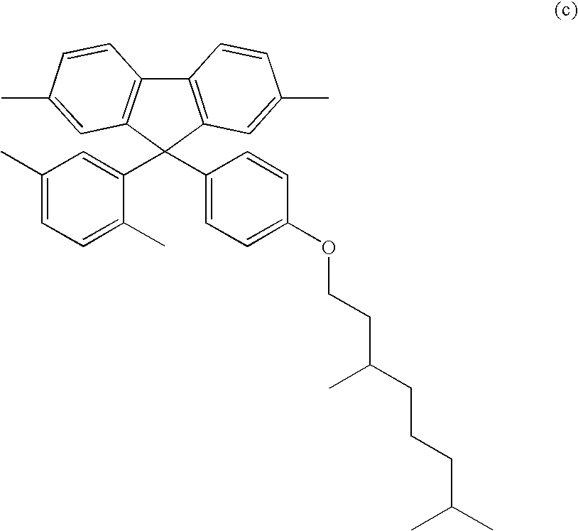
[0060] Monomers according to the invention may be prepared in accordance with the following scheme:

modelled examples

[0061] The effect of appending various groups to the phenyl rings of 9,9-diphenylfluorene repeat unit HOMO and LUMO levels was calculated using AM1 from the AMPAC software package (1) and ZINDO calculations from the Gaussian software package (2). [0062] 1) AM1 in Ampac program package [0063]Ampac 5.0 User's Manual, © 1994 Semichem, 7128 Summit, Shawnee, Kans. 66216 [0064] 2) ZINDO from Gaussian software: [0065] Gaussian 98, Revision A.9, [0066] M. J. Frisch, G. W. Trucks, H. B. Schlegel, G. E. Scuseria, [0067] M. A. Robb, J. R. Cheeseman, V. G. Zakrzewski, J. A. Montgomery, Jr., [0068] R. E. Stratmann, J. C. Burant, S. Dapprich, J. M. Millam, [0069] A D. Daniels, K. N. Kudin, M. C. Strain, O. Farkas, J. Tomasi, [0070] V. Barone, M. Cossi, R. Cammi, B. Mennucci, C. Pomelli, C. Adamo, [0071] S. Clifford, J. Ochterski, G. A. Petersson, P. Y. Ayala, Q. Cui, [0072] K. Morokuma, D. K. Malick, A. D. Rabuck, K. Raghavachari, [0073] J. B. Foresman, J. Cioslowski, J. V. Ortiz, A. G. Baboul, [...


PUM

PropertyMeasurementUnit
Dynamic viscosityaaaaaaaaaa
Transport propertiesaaaaaaaaaa
Charge carrieraaaaaaaaaa

Abstract

A polymer formed from optionally substituted first repeat units of formula (I) wherein Ar is selected from (a) aromatic hydrocarbon substituted with at least one electron withdrawing group or electron withdrawing heteroaryl. The polymers have application in electroluminescent devices.

Description

FIELD OF THE INVENTION [0001] This invention relates to semiconductive polymers, their synthesis and use in optical devices. BACKGROUND OF THE INVENTION [0002] Electroactive polymers are now frequently used in a number of optical devices such as in polymeric light emitting diodes (“PLEDs”) as disclosed In WO 90 / 13148, photovoltalc devices as disclosed In WO 96 / 16449 and photodetectors as disclosed in U.S. Pat. No. 5,523,555. [0003] A typical PLED comprises an organic electroluminescent layer located between an anode and a cathode. In operation, holes are injected Into the device through the anode and electrons are injected into the device through the cathode. Holes enter the highest occupied molecular orbital (“HOMO”) of the electroluminescent polymer and electrons enter the lowest unoccupied molecular orbital (“LUMO”) and then combine to form an exciton which undergoes radiative decay to give light. The colour of light emitted from the electroluminescent polymer depends on its HOMO...

Claims


Application Information

Patent Timeline
IPC IPC(8): H01L51/54C08G61/00C09K11/06H05B33/14C08G61/02H10K99/00
CPCC08G61/02Y10S428/917C08G2261/146C08G2261/148C08G2261/149C08G2261/514C08G2261/5222C09K11/06C09K2211/1416C09K2211/1425C09K2211/1433H01L51/0039H01L51/0043H01L51/0059H01L51/50H05B33/14C08G2261/124H10K85/115H10K85/151H10K85/631H10K50/10C08G61/00G02B1/04H10K50/00
Inventor BURROUGHES, JEREMYFRIEND, RICHARDHFODEN, CLARE
Owner CAMBRIDGE DISPLAY TECH LTD
Learn More