Eureka AIR delivers breakthrough ideas for toughest innovation challenges, trusted by R&D personnel around the world.

Internal power supply control method, internal power supply circuit, and semiconductor device

Inactive Publication Date: 2006-10-12
ELPIDA MEMORY INC
View PDF11 Cites 0 Cited by
  • Summary
  • Abstract
  • Description
  • Claims
  • Application Information

AI Technical Summary

Benefits of technology

[0011] It is therefore an object of the present invention to provide an internal power supply control method which does not require modification of the layout for supplying an appropriate amount of power to a DLL circuit.
[0016] The small power supply control according to the present invention controls an internal power supply circuit which supplies power to an electronic circuit having characteristics that the current consumption thereof substantially varies depending on the frequency of an externally-input clock. Therefore, the internal power supply circuit is divided into a plurality of small power supply circuits. The internal power supply circuit detects a frequency of a clock to be supplied to the electronic circuit, and controls the connection of the plurality of small power supply circuits according to the detected clock frequency. The provision of the internal power supply circuit according to the present invention makes it possible to automatically adjust the number of small power supply circuits to be connected to the electronic circuit as required. The present invention thus has an advantageous effect that the user is not required anymore to do the wiring work depending upon whether the clock to be used is a high-speed clock or a low-speed clock for minimizing the current consumption.

Problems solved by technology

As is well known, the power consumption is increased as the clock frequency becomes higher.
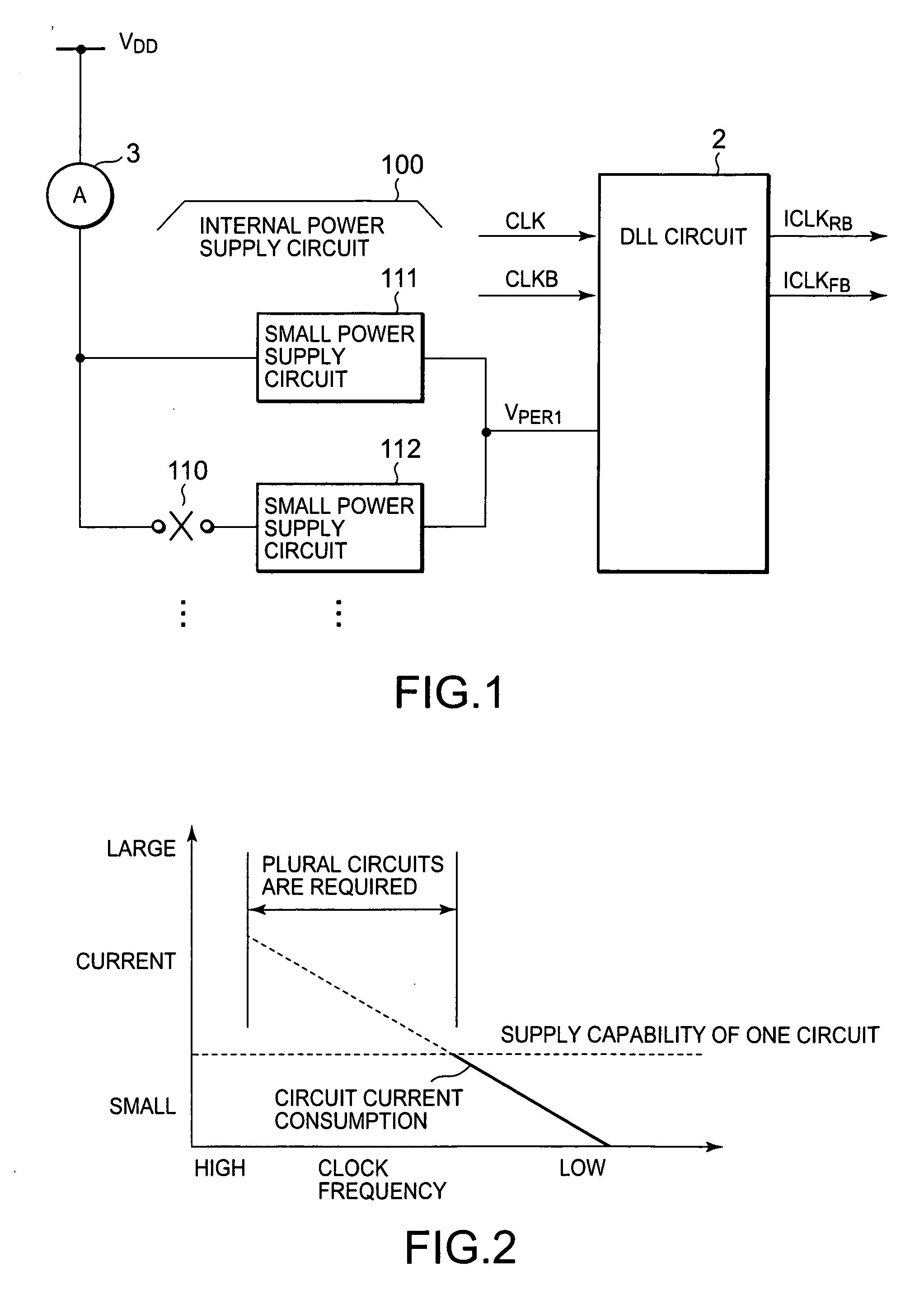
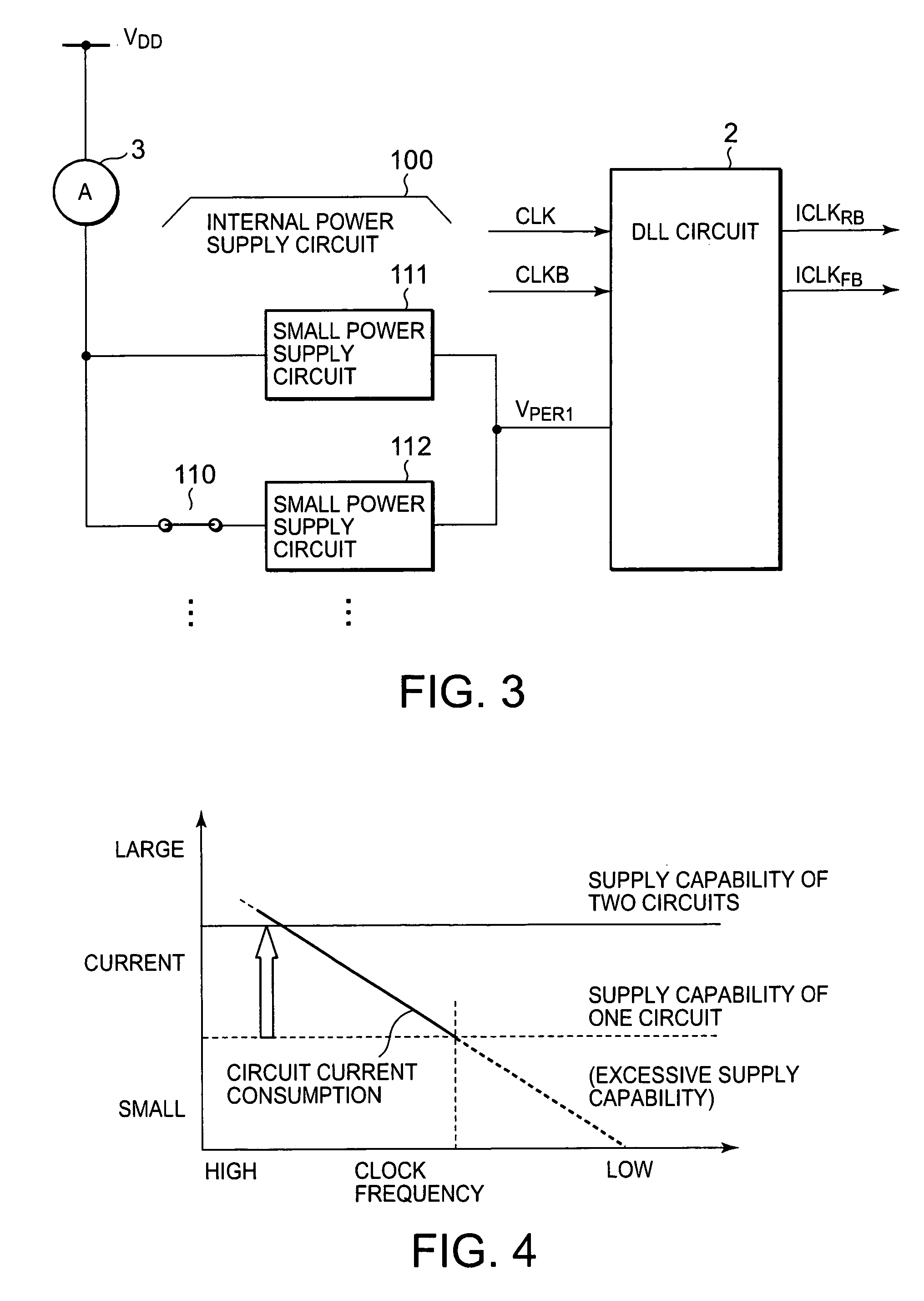
However, the circuit configuration of FIG. 1 consumes low current since no current is supplied to the small power supply circuit 112.
However, if this circuit configuration is used for operation with low-speed clocks, the supply capability will exceed the capability actually required, resulting in consumption of unnecessary current.
Using these circuit configurations, however, the user is required to switch connection of the internal power supply formed on a chip depending upon the user's desired operation, either with high-speed clocks or with low-speed clocks.
Such switching is not possible or can not be carried out by the user.
Consequently, the user is required to select an appropriate internal power supply, but this is difficult or impossible for the user.

Method used


Image

  • Internal power supply control method, internal power supply circuit, and semiconductor device
  • Internal power supply control method, internal power supply circuit, and semiconductor device
  • Internal power supply control method, internal power supply circuit, and semiconductor device

Examples


first embodiment

[0033] A first embodiment of the present invention will be described with reference to FIGS. 5 and 6 together.

[0034]FIG. 5 shows, as a first embodiment of the present invention, a configuration of a functional block including an internal power supply circuit 1 and peripheral circuits thereof. The configuration shown in FIG. 5 includes the internal power supply circuit 1, a delay locked loop (DLL) circuit 2, and an external current source A3. The external current source A3 is a circuit which receives an external power supply voltage VDD and supplies current to the internal power supply circuit 1.

[0035] The internal power supply circuit 1 is composed of a basic power supply circuit 11, an additional power supply circuit 12, and a frequency determination circuit 20. The internal power supply circuit 1 is arranged between the DLL circuit 2 and the external current source A3 having an external power supply voltage VDD. Receiving the external power supply voltage VDD, the internal power...

second embodiment

[0057] A second embodiment of the present invention will now be described with reference to FIGS. 10 to 13 together.

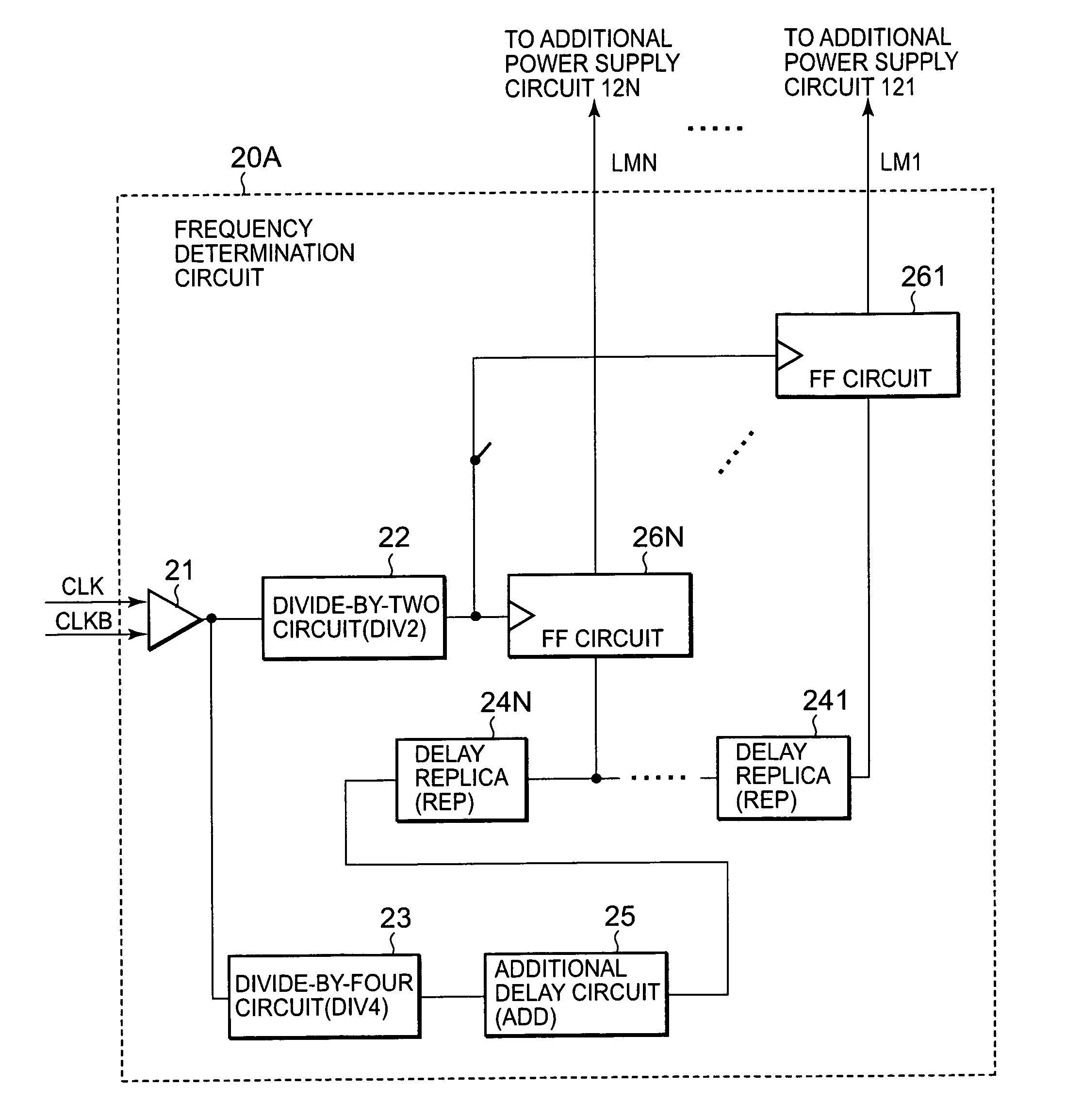
[0058] An internal power supply circuit 1A shown in FIG. 10 has a number N of additional power supply circuits 121 to 12N. A frequency determination circuit 20A controls the connection to each of the N additional power supply circuits 121 to 12N. The other composing elements have the same functions as those described with reference to FIG. 5 and, therefore, the description thereof will be omitted. The basic power supply circuit 11 and the additional power supply circuit 121 to 12N have an identical power supply capacity.

[0059] The additional power supply circuits 121 to 12N are essentially the same as the additional power supply circuit 12 described with reference to FIG. 5. Under the control of the frequency determination circuit 20A, each of the additional power supply circuits 121 to 12N is switched on or off to connect or disconnect the external power supply to t...


PUM


Abstract

When a DLL circuit using a clock is employed, the internal power supply circuit is arranged between the external power supply and the DLL circuit. The internal power supply circuit supplies power from the external power supply after reducing the voltage thereof. The internal power supply circuit is divided into a basic power supply circuit and an additional power supply circuit. The internal power supply circuit further includes a frequency determination circuit, which samples the clock to detect the frequency thereof, and generates a determination signal based on the detected frequency. Based on the determination signal, the internal power supply circuit controls the connection or disconnection of the additional power supply circuit. The basic power supply circuit and the additional power supply circuit are activated in a high frequency range, whereas only the basic power supply circuit is activated in a low frequency range.

Description

[0001] This application claims priority to prior Japanese patent application JP 2005-88465, the disclosure of which is incorporated herein by reference. BACKGROUND OF THE INVENTION [0002] This invention relates to an internal power supply control method, an internal power supply circuit employing this control method, and a semiconductor device including such an internal power supply circuit. [0003] In recent years, there have been developed microprocessors operable at higher speeds and yet with lower power consumption. This trend is increasing the demand for chips having a higher data transferring speed and yet low power consumption. In response to such demand of the users, chips are now being developed which are capable of carrying out high speed operation and yet can suppress the power consumption. It is particularly essential to reduce the current consumption of delay locked loop (DLL) circuits operating at high speeds. As is well known, the power consumption is increased as the ...

Claims


Application Information

Patent Timeline
IPC IPC(8): H03B19/00
CPCG06F1/263
Inventor AKIYAMA, TAKESHISHIMIZU, YUSUKEIDEI, YOJI
Owner ELPIDA MEMORY INC
Why Eureka
Eureka Blog
Learn More