Eureka AIR delivers breakthrough ideas for toughest innovation challenges, trusted by R&D personnel around the world.

Driving Organic Light-Emitting Diodes with Pulse Width Modulation

A pulse width modulation, light emitting diode technology, applied in electroluminescence light source, light source, electric light source and other directions, can solve the problem of affecting OLED capacitance, etc., and achieve the effect of improving accuracy and accurate detection

Inactive Publication Date: 2016-06-15
特里多尼克股份有限公司
View PDF6 Cites 0 Cited by
  • Summary
  • Abstract
  • Description
  • Claims
  • Application Information

AI Technical Summary

Problems solved by technology

In addition, the roughly 100 nm thickness of the organic layer between the electrodes also affects the capacitance of the OLED

Method used


Image

  • Driving Organic Light-Emitting Diodes with Pulse Width Modulation
  • Driving Organic Light-Emitting Diodes with Pulse Width Modulation
  • Driving Organic Light-Emitting Diodes with Pulse Width Modulation

Examples


Embodiment Construction

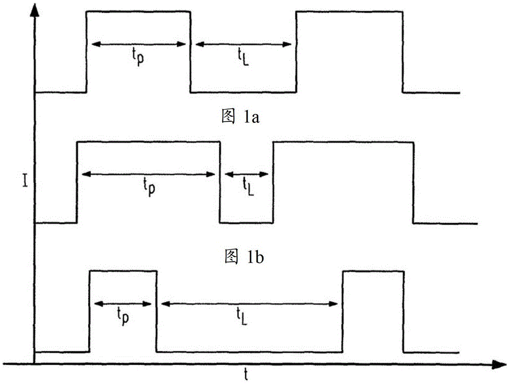
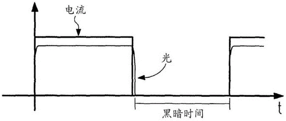
[0063] Figure 5 A driver circuit 1 according to the invention is shown, which can implement the driver method according to the invention. In this case, the driver circuit 1 is connected to the OLED 2 . Here, the drive circuit 1 includes a drive unit 3 that supplies current to the OLED. The power supply to OLED2 takes place by means of pulse width modulation (PWM). The drive unit 3 is controlled by a control unit 4 . The control unit 4 controls the drive unit 3 in such a way that it adjusts the PWM current pulses, in particular their amplitude and pulse width t P , and to adjust the PWM vacancy, especially its width t L . Furthermore, the control unit 4 is suitable, for example, as Figure 4 As shown, the falling edge at the end of the PWM current pulse of OLED2 is shortened using circuit technology, for example by short-circuiting. This avoids afterglow of OLED2 in PWM vacancy. To this end, for example, a low-impedance jumper conductor is connected in parallel to OLED...


PUM


Abstract

The invention makes use of the effect that the high parasitic capacitance of the OLED leads to a prolonged drop in luminous intensity after each PWM current pulse during PWM operation. This can advantageously be exploited by the first method, which prevents the luminous intensity from falling to zero during the PWM vacancy in order to avoid the so-called beading effect when the OLED is in motion. By the second method, OLED afterglow is suppressed to achieve better color characteristics without considering the beading effect. For this purpose, the falling edge can be shortened or adjusted in a controlled manner. In a third method, this effect is taken into account when the OLED is switched on in such a way that the rising edge is initially shortened by an excessively high drive current in order to achieve a rapid attainment of the setpoint value of the luminous intensity. These methods are implemented by a drive circuit or control unit according to the invention.

Description

technical field [0001] The invention relates to a method and a circuit for driving organic light-emitting diodes by means of pulse width modulation. In particular, the present invention advantageously uses the parasitic capacitance of the OLED to drive the OLED. Background technique [0002] Organic light-emitting diodes, referred to as OLEDs (abbreviations for "OrganicLight-EmittingDiode" in English), are thin-film-shaped, light-emitting components made of organic and semiconductor materials. The difference between them and inorganic light-emitting diodes (LEDs) is that the current density and optical density are less and do not require single crystal material. Because OLEDs can be pressed onto almost any material, they offer significant cost savings over LCD technology. Flexible carrier materials (flexible substrates, films) can also be used for OLEDs, thus opening up completely new possibilities. [0003] A drive circuit is used to drive the OLED. In this case, the OL...

Claims


Application Information

Patent Timeline
Patent Type & Authority Patents(China)
IPC IPC(8): H05B33/08H05B44/00
CPCH05B45/60Y02B20/30
Inventor 爱德华多·佩雷拉迈克尔·齐默尔曼
Owner 特里多尼克股份有限公司
Why Eureka
Eureka Blog
Learn More