
Downhole position locating device with fluid metering feature

a technology of position locating device and fluid metering, which is applied in the direction of drilling casing, drilling pipe, and well accessories, etc., can solve the problems of limited material level, dragging of work string, and limit of stress that can be applied to the collet head, so as to reduce the slingshot effect, constant force, and reduce the effect of applied for

Active Publication Date: 2006-10-12
BAKER HUGHES INC
View PDF10 Cites 45 Cited by
  • Summary
  • Abstract
  • Description
  • Claims
  • Application Information

AI Technical Summary

Benefits of technology

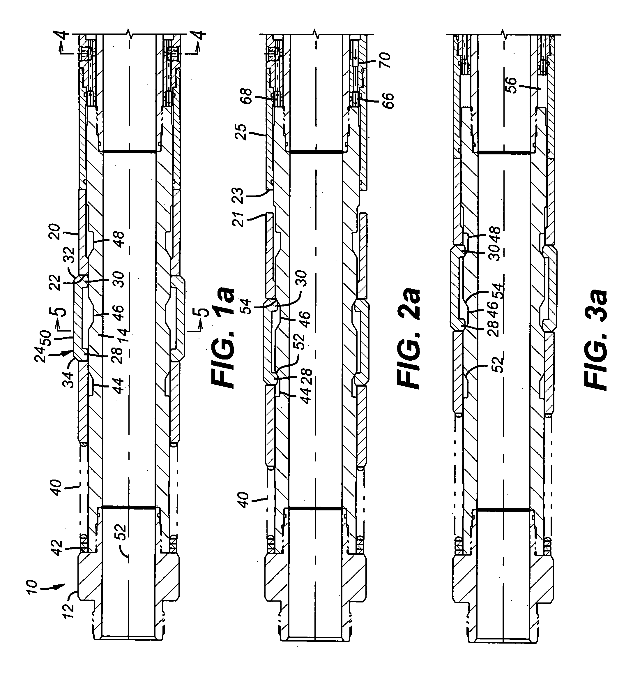
The patent describes a tool that can be used in a wellbore for multiple purposes. It has dogs that can engage a collar or a restriction in the wellbore. These dogs can retract to clear restrictions when the tool is being tripped into the well. When the tool reaches a collar, the dogs engage and an upward pull on the mandrel displaces fluid through a restriction to allow enough time to get a meaningful surface signal of the overpull force. Afterward, the applied force can be reduced as the dogs release at a lower applied force to reduce the slingshot effect. This tool can also be used to keep a constant force on a bottom hole assembly during offshore drilling where a heave compensator is employed.

Problems solved by technology

There are several issues with this design.
In deep wells with a significant amount of deviation there is a substantial risk of drag of the work string in the surrounding tubular so that the overpull applied could be the force required to dislodge the work string as opposed to a pull on the collets that may not even have landed in the locator groove of the collar in question.
Another problem is the limit of stress that can be applied to the collet heads that are in the locating groove.
While the collet structure can be made thicker the problem there is that the material may be limited in the level of stress that can be endured on the trapped collet heads.
Another issue is limited space and tool diameter restriction required to actually deliver the tool to the collar in interest.
Thus making the parts thicker may not be sufficiently helpful to increase the overall rating toward the desired pulling force required or there may not be the room required to go this route.
Another issue with the collet based systems is that upon release there is a slingshot effect as the stored potential energy in the applied pulling force on the work string is suddenly released as the collets become unsupported when a predetermined pulling force is reached.

Method used


Image

  • Downhole position locating device with fluid metering feature
  • Downhole position locating device with fluid metering feature
  • Downhole position locating device with fluid metering feature

Examples


Embodiment Construction

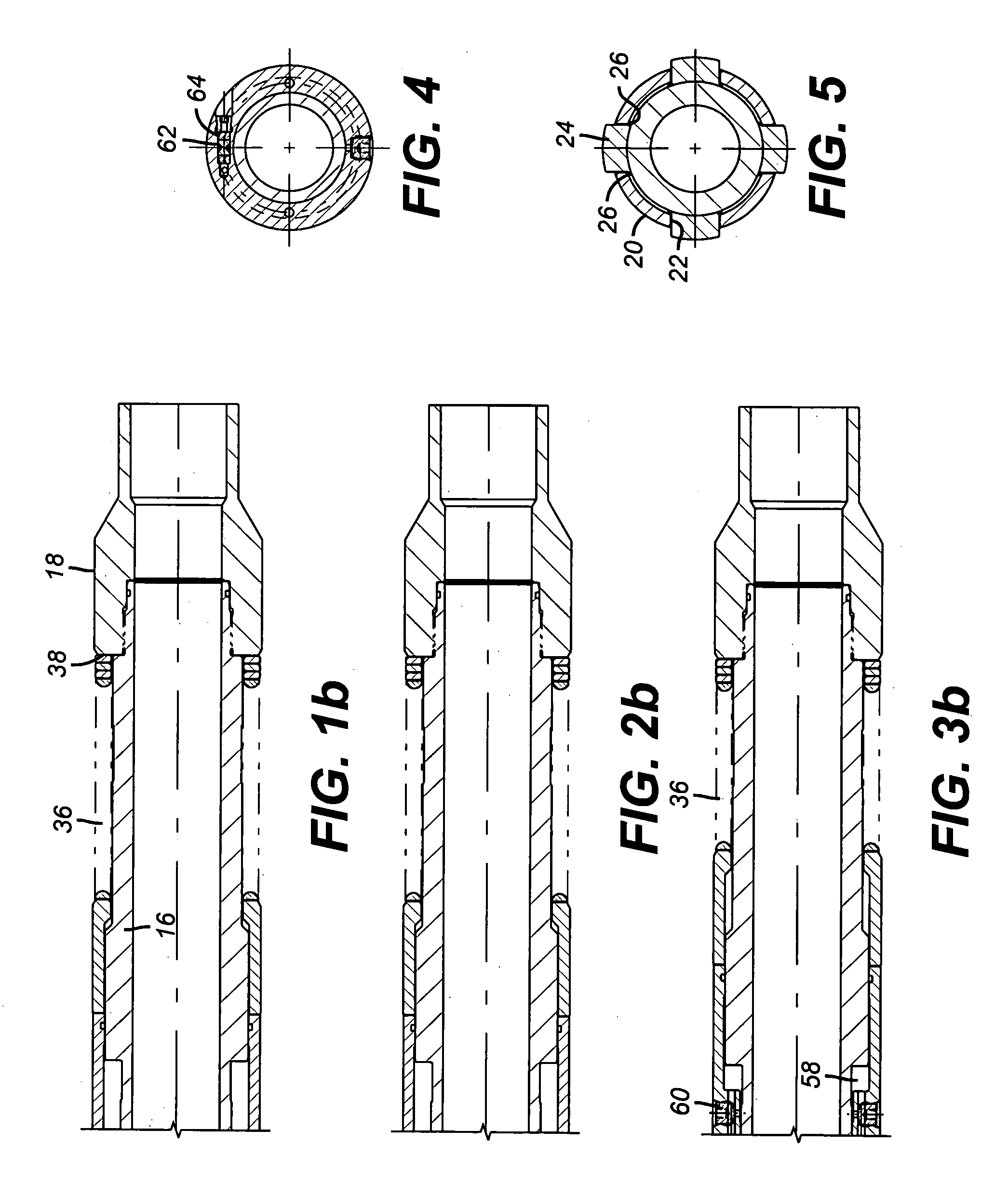
[0011] The mandrel 10 is made up of top sub 12, upper body 14, lower body 16 and bottom sub 18. These pieces are preferably threaded together but may be attached in other ways. More or fewer pieces can be used to define the mandrel 10. An outer sleeve 20 has a window 22 for each dog 24 that is used. One or more dogs 24 can be used. Dogs 24 have tabs 26 at opposed ends, as best seen in FIG. 5 to limit the outward travel of the dogs 24 with respect to window 22. FIG. 1a shows the dog 24 in section. In the preferred form of dog 24, it is generally U-shaped having a pair of inwardly oriented legs 28 and 30. On the trip into the well surface 32 on dog 24 will encounter an obstacle. On the trip out of the well, surface 34 on dog 24 will encounter an obstacle.

[0012] Sleeve 20 is mounted to slide over mandrel 10. It is biased uphole by spring 36 that bears on surface 38 of bottom sub 18. Spring 40 bears on surface 42 of top sub 12 and applies an opposing force to sleeve 20 than spring 36. ...


PUM


Abstract

A tool for multiple purposes features one ore more dogs that can engage a collar groove or restriction sub in the wellbore. The dogs are extendable through a sleeve biased in opposed directions and are supported from a mandrel. The dogs can retract into mandrel grooves to clear restrictions on the trip into the well. On the way up to a collar that has just been passed, the dogs engage and an upward pull on the mandrel displaces fluid through a restriction to allow enough time to get a meaningful surface signal of the overpull force. Thereafter, the applied force can be reduced as the dogs release at a lower applied force to reduce the slingshot effect. The tool can be inverted and used to keep a constant force on a bottom hole assembly during offshore drilling where a heave compensator is employed.

Description

FIELD OF THE INVENTION [0001] The field of this invention is devices that can be used downhole to locate collars and / or other features in the wellbore and give a surface signal of such location or in a reverse orientation can be used to apply a predetermined load on a bottom hole assembly (BHA). BACKGROUND OF THE INVENTION [0002] Frequently the specific depth of collars and / or other features in the wellbore in a casing string needs to be located with an indication at the surface that the collar has been properly located. In the past this function has been approached with a tool delivered on a string that has one or more collets. The collets and the mandrel that backs them up are configured to allow the collets to remain in an unsupported position for downhole tripping. After the desired collar is reached the tool with the collets is further advanced downhole beyond a locating groove in the collar that is of interest. The tool is then picked back up to engage the collar. Doing this t...

Claims


Application Information

Patent Timeline
Patent Type & Authority Applications(United States)
IPC IPC(8): E21B23/04E21B47/09
CPCE21B47/09E21B23/02
Inventor CORONADO, MARTIN P.
Owner BAKER HUGHES INC
Learn More