Startup controller for in-cylinder injection internal combustion engine

Active Publication Date: 2006-10-12
DENSO CORP
View PDF2 Cites 21 Cited by
  • Summary
  • Abstract
  • Description
  • Claims
  • Application Information

AI Technical Summary

Benefits of technology

[0010] It is an object of the present invention to provide a startup controller for an in-cylinder injection internal combustion engine capable of shortening a startup time without taking measures of increasing the size of a high-pressure pump or decreasing the volume of a high-pressure fuel pipe or delivery pipe, thereby meeting requirements such as improved startup properties and reduced emissions at startup.
[0013] In view of this respect, even if the actual fuel pressure at the injection setting has not yet reached a predetermined fuel pressure, the controller according to an aspect of the present invention performs injection, provided that it is estimated that the fuel pressure at the injection start, which is estimated at the injection setting, will have increased to the fuel pressure suitable for the startup in the process of cranking of the internal combustion engine with a starter for the startup. Accordingly, a startup time can be shortened without taking the measures of increasing the size of the high-pressure pump or decreasing the volume of the high-pressure fuel pipe or delivery pipe, thereby meeting the requirements such as improved startup properties and reduced emissions at the startup.

Problems solved by technology

However, in some cases, even if an actual fuel pressure at the injection setting has not increased to a fuel pressure suitable for the startup, the fuel pressure can reach the fuel pressure suitable for the startup at a subsequent injection start because of fuel discharge from a high-pressure pump caused by cranking.

Method used


Image

  • Startup controller for in-cylinder injection internal combustion engine
  • Startup controller for in-cylinder injection internal combustion engine
  • Startup controller for in-cylinder injection internal combustion engine

Examples


second embodiment

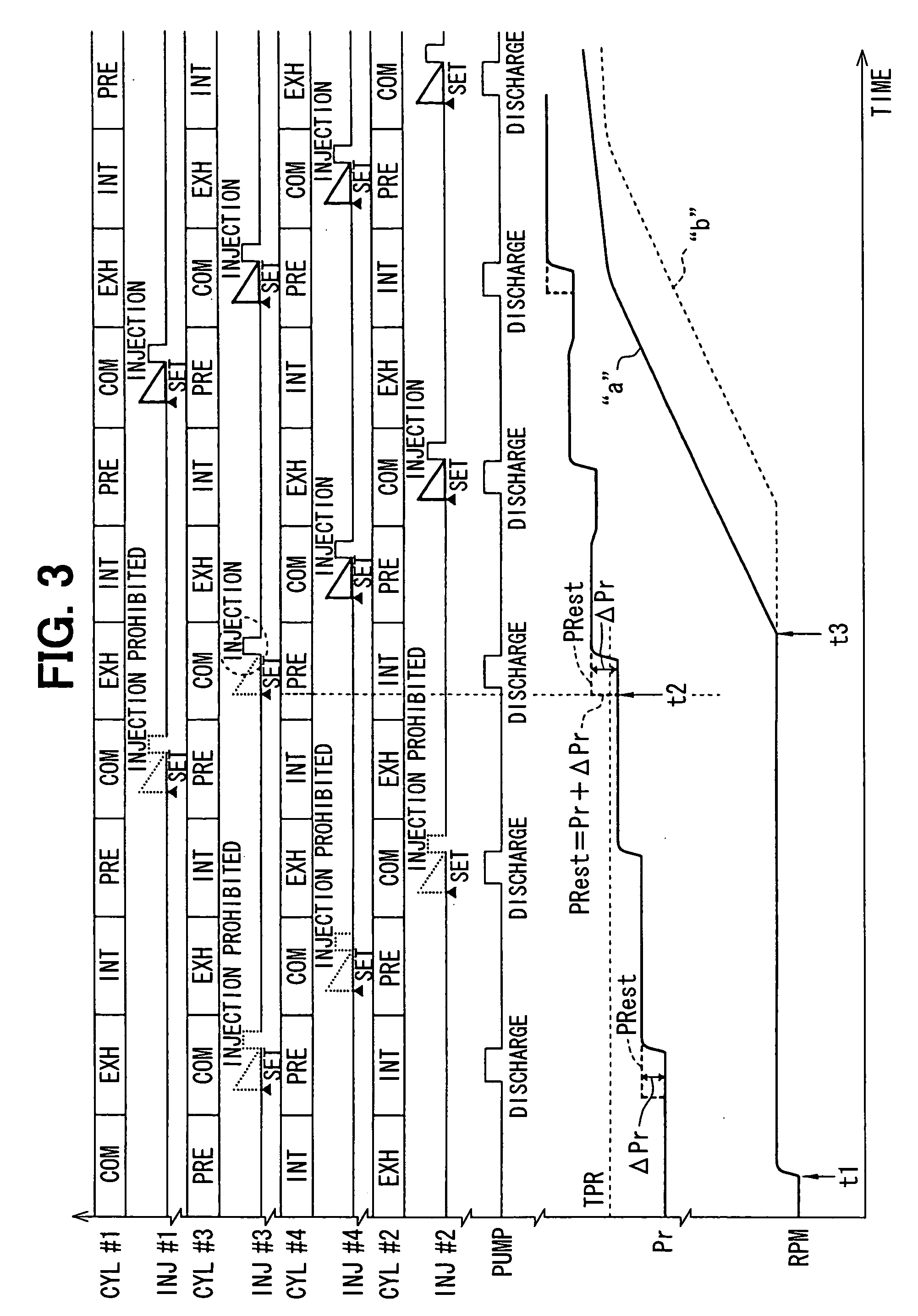
[0077] A fuel pressure increment calculation routine shown in FIG. 12 is a modification of the above-mentioned fuel pressure increment calculation routine of FIG. 10. The process at Step S306 is replaced with two steps of Steps S306a and S306b, but the other processes are the same as those in the fuel pressure increment calculation routine of FIG. 10.

[0078] In the fuel pressure increment calculation routine shown in FIG. 12, the process goes to Step S305 after completion of an initial energization (first discharge) of the high-pressure pump 14. Step S305 reads in a fuel pressure Pr sensed by the fuel pressure sensor 29 at the current time (when the first discharge is finished). Then, the process goes to Step S306a, where a correction factor K is calculated. Step S306a may calculate the correction factor K in accordance with the fuel temperature TF at the injection setting by using a map or formula that uses as a parameter the fuel temperature TF at the injection setting as shown in...

first embodiment

[0080] The process then goes to Step S307, where information about the completion of the calculation of the fuel pressure increment ΔPr is stored. Thus, this routine terminates. The other processes are the same as those in the

[0081] The actual fuel pressure increment ΔPr varies depending on the fuel pressure Pr and the fuel temperature TF. Therefore, in the second example embodiment, the fuel pressure difference (Pr−P0) across the discharge stroke of the high-pressure pump 14 is corrected with the correction factor K depending on the sensed fuel pressure Pr and / or fuel temperature TF at the injection setting. Thus, the fuel pressure increment ΔPr from the injection setting to the injection start is estimated. Therefore, the estimation accuracy of the fuel pressure at the injection start is improved further than the first example embodiment.


PUM


Abstract

A startup controller calculates a fuel pressure difference across a discharge stroke of a high-pressure pump at an end of an initial discharge after cranking is started. At the injection setting, the startup controller estimates a fuel pressure increment from an injection setting to an injection start based on the fuel pressure difference. The startup controller adds the fuel pressure increment to a fuel pressure sensed at the injection setting to estimate a fuel pressure at the injection start. The startup controller determines whether to perform or to prohibit the injection based on whether the estimated fuel pressure at the injection start is equal to or higher than an injection permission fuel pressure.

Description

CROSS REFERENCE TO RELATED APPLICATION [0001] This application is based on and incorporates herein by reference Japanese Patent Application No. 2005-111529 filed on Apr. 8, 2005. BACKGROUND OF THE INVENTION [0002] 1. Field of the Invention [0003] The present invention relates to a startup controller for an in-cylinder injection internal combustion engine having a function of promptly increasing fuel pressure at a startup. [0004] 2. Description of Related Art [0005] An in-cylinder injection engine, which injects fuel directly into a cylinder, takes a short time from injection to combustion compared to an intake port injection engine, which injects fuel into an intake port. The in-cylinder injection engine does not have enough time to atomize the injected fuel. Therefore, the in-cylinder injection engine has to elevate injection pressure to atomize the injected fuel. The in-cylinder injection engine is so constructed that fuel pumped up from a fuel tank by a low-pressure pump is press...

Claims


Application Information

Patent Timeline
IPC IPC(8): F02B5/00F02M51/00G06F19/00F02D41/06F02D45/00F02P5/15
CPCF02D41/062F02M63/0225F02D2200/0604F02D41/3845
Inventor FUKASAWA, OSAMU
Owner DENSO CORP
Why Eureka
Try Eureka