
Disk array apparatus and method of controlling the same

a technology of array apparatus and array memory, which is applied in the direction of program control, multi-programming arrangements, instruments, etc., can solve the problems of high cost relative to performance improvement, high cost, and reduced cost performance, so as to achieve high cost, reduce cost, and increase assembly

Inactive Publication Date: 2006-10-05
HITACHI LTD
View PDF5 Cites 48 Cited by
  • Summary
  • Abstract
  • Description
  • Claims
  • Application Information

AI Technical Summary

Benefits of technology

[0009] However, the disk array apparatus having a plurality of CPUs requires an expensive shared memory to share information among the CPUs. Thus, the cost is high relative to the performance improvement, and there is a problem that the cost-performance is reduced. In addition, since each CPU requires a clock or a power supply circuit, the assembly is enlarged, and thus, the production cost also increases.
[0011] The present invention has been devised to solve the problems described above, and an object of the present invention is to provide a disk array apparatus that is improved in cost-performance, prevents interaction among controls, and allows efficient use of resources.

Problems solved by technology

However, the disk array apparatus having a plurality of CPUs requires an expensive shared memory to share information among the CPUs.
Thus, the cost is high relative to the performance improvement, and there is a problem that the cost-performance is reduced.
In addition, since each CPU requires a clock or a power supply circuit, the assembly is enlarged, and thus, the production cost also increases.
Therefore, if the system management function of the disk array apparatus goes down due to a security crack or the like, for example, it may cause another function to go down.

Method used


Image

  • Disk array apparatus and method of controlling the same
  • Disk array apparatus and method of controlling the same
  • Disk array apparatus and method of controlling the same

Examples


Embodiment Construction

[0028] Best modes for carrying out the present invention will be described in detail.

[0029] In the following, a disk array apparatus and a method of controlling the disk array apparatus according to an embodiment of the present invention will be described with reference to the drawings.

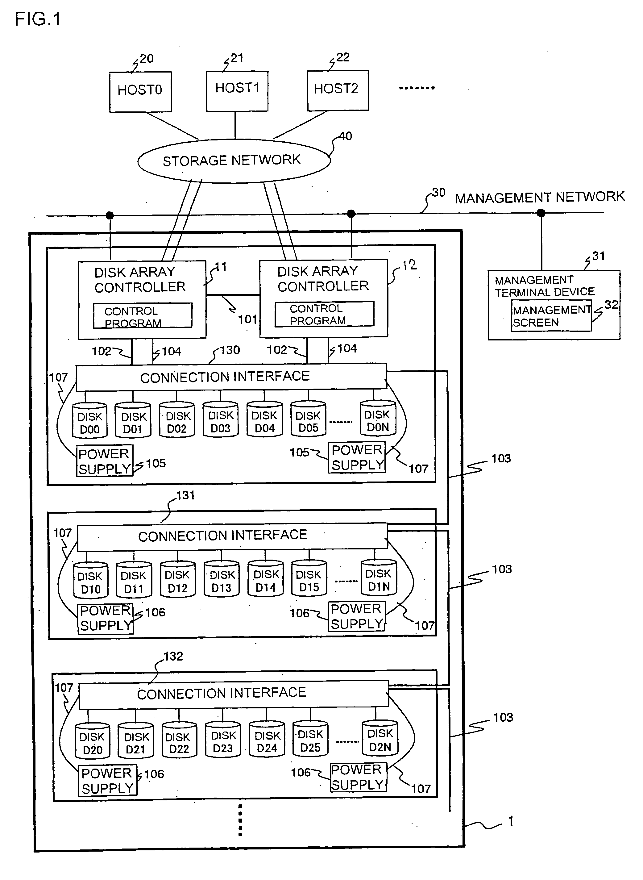
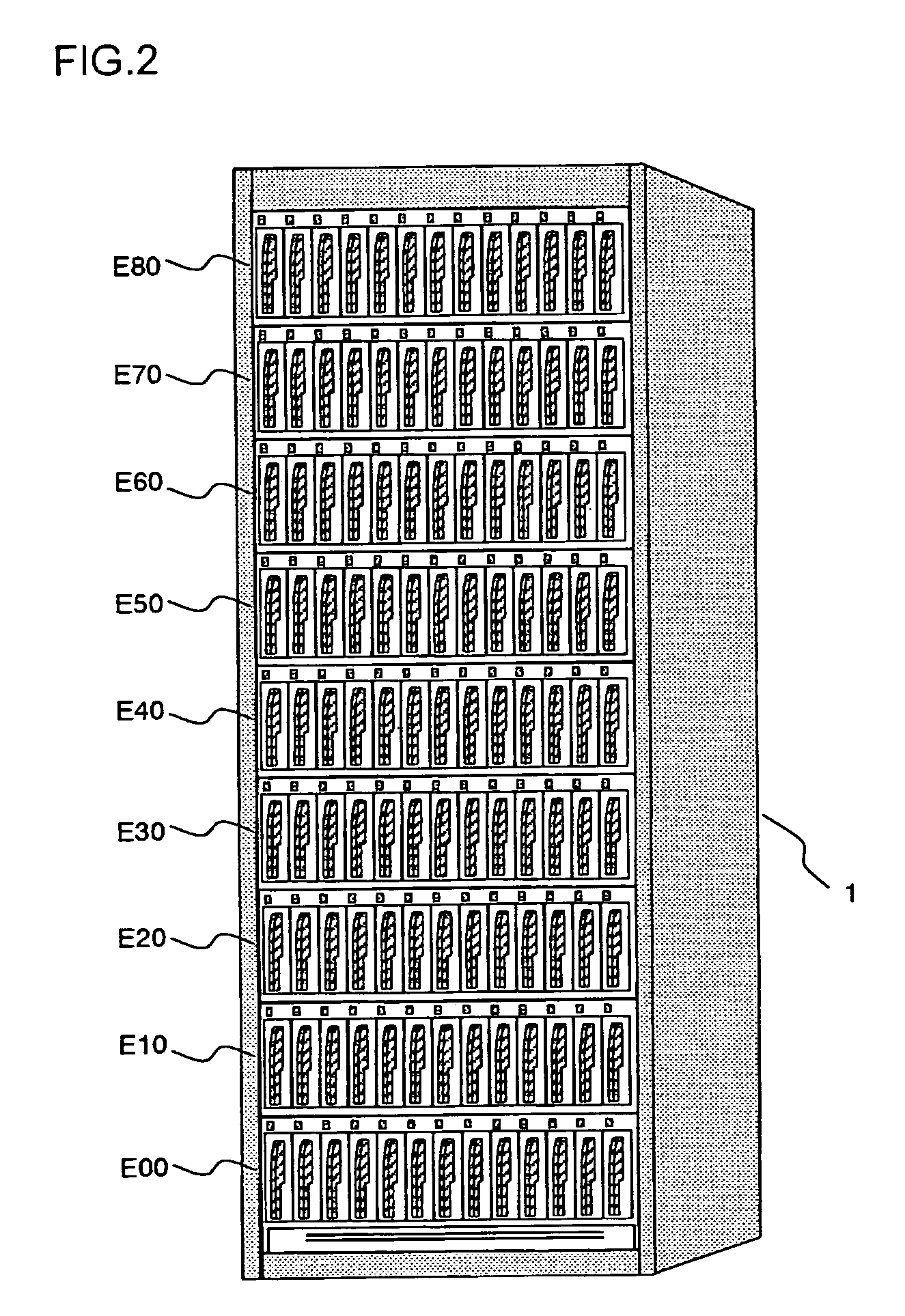
[0030] Now, an embodiment 1 will be described. An arrangement of a disk array apparatus according to this embodiment will be described with reference to FIGS. 1 to 8. FIG. 1 is a schematic diagram showing an arrangement of the disk array apparatus according to this embodiment. FIG. 2 is a schematic view of the disk array apparatus according to this embodiment. FIG. 3 is a block diagram showing a functional arrangement of a disk array controller of the disk array apparatus according to this embodiment, and FIG. 4 is a schematic view of the disk array controller. FIG. 5 is a block diagram showing a functional arrangement of a CPU incorporating a plurality of processor cores (MPU cores) mounted on the ...


PUM


Abstract

To efficiently manage performance resources while preventing a failure of a control processing from affecting another control processing in a disk array apparatus. A disk array apparatus 1 has a disk array controller 11, the disk array controller 11 has a CPU incorporating a plurality of processor cores 1110 that cannot be physically separated from each other, each processor core serves as an unit processor, one unit processor manages the unit processors separately, allocates a self-contained control program to each unit processor in such a manner that the operation of the unit processor can be terminated appropriately or in such a manner that the unit processor can operate until the operation of the whole CPU is terminated, and manages the processing load or processing status of the allocated control program on a unit-processor basis.

Description

[0001] The present application is based on and claims priority of Japanese patent application No. 2005-097505 filed on Mar. 30, 2005, the entire contents of which are hereby incorporated by reference. BACKGROUND OF THE INVENTION [0002] 1. Field of the Invention [0003] The present invention relates to a disk array apparatus incorporating a plurality of disk units and a method of controlling the disk array apparatus. [0004] 2. Description of the Related Art [0005] As a technique for improving the speed of access to data and the reliability of a disk array apparatus by providing a plurality of disk units, the redundant array of independent disks (RAID) has been known. Typically, a disk array controller is responsible for the RAID control, and the performance improvement of the disk array controller has been pursued. [0006] The disk array controller has a CPU for executing a processing program for the array controller. According to an approach to the performance improvement, a plurality...

Claims


Application Information

Patent Timeline
IPC IPC(8): G06F12/16G06F11/00G06F15/177
CPCG06F3/061G06F9/5088G06F3/067G06F3/0658
Inventor ARAI, MASAHIROMATSUNAMI, NAOTO
Owner HITACHI LTD
Learn More