Vehicular brake control apparatus and control method therefor

a control apparatus and brake technology, applied in the direction of braking systems, cycle brakes, cycle equipments, etc., can solve the problems of not being able to achieve sporty running, not being able to fit the driver's intention, and not being able to achieve good brake feeling, etc., to achieve normal braking operation, good brake feeling, and stable vehicle behavior

Active Publication Date: 2006-10-05
HITACHI ASTEMO LTD
View PDF5 Cites 6 Cited by
  • Summary
  • Abstract
  • Description
  • Claims
  • Application Information

AI Technical Summary

Benefits of technology

[0044] According to this control method, when the normal running state in which the anti-lock brake control is not performed, the normal braking operation is allowed. On the other hand, in the running state where the wheel likely falls into the locked state, the brake force is interlockingly applied to the brake system of the wheel which is other than the wheel to which the anti-lock brake control performed, to thereby contribute to stabilize the behavior of the vehicle.
[0045] According to the brake control apparatus and the control method therefore according to the invention, a good brake feeling can be obtained and the behavior of the vehicle can be stabilized.

Problems solved by technology

Thus, in such the conventional brake control apparatus, unlike the conventional bar handle type vehicle, the brake operations of the front and rear wheels can not be performed independently based on a driver's intention, so that a good brake feeling can not be obtained.
Further, a sporty running etc. fitting for a driver's intention can be not realized due to such the interlocking brake operation.

Method used


Image

  • Vehicular brake control apparatus and control method therefor
  • Vehicular brake control apparatus and control method therefor
  • Vehicular brake control apparatus and control method therefor

Examples


Embodiment Construction

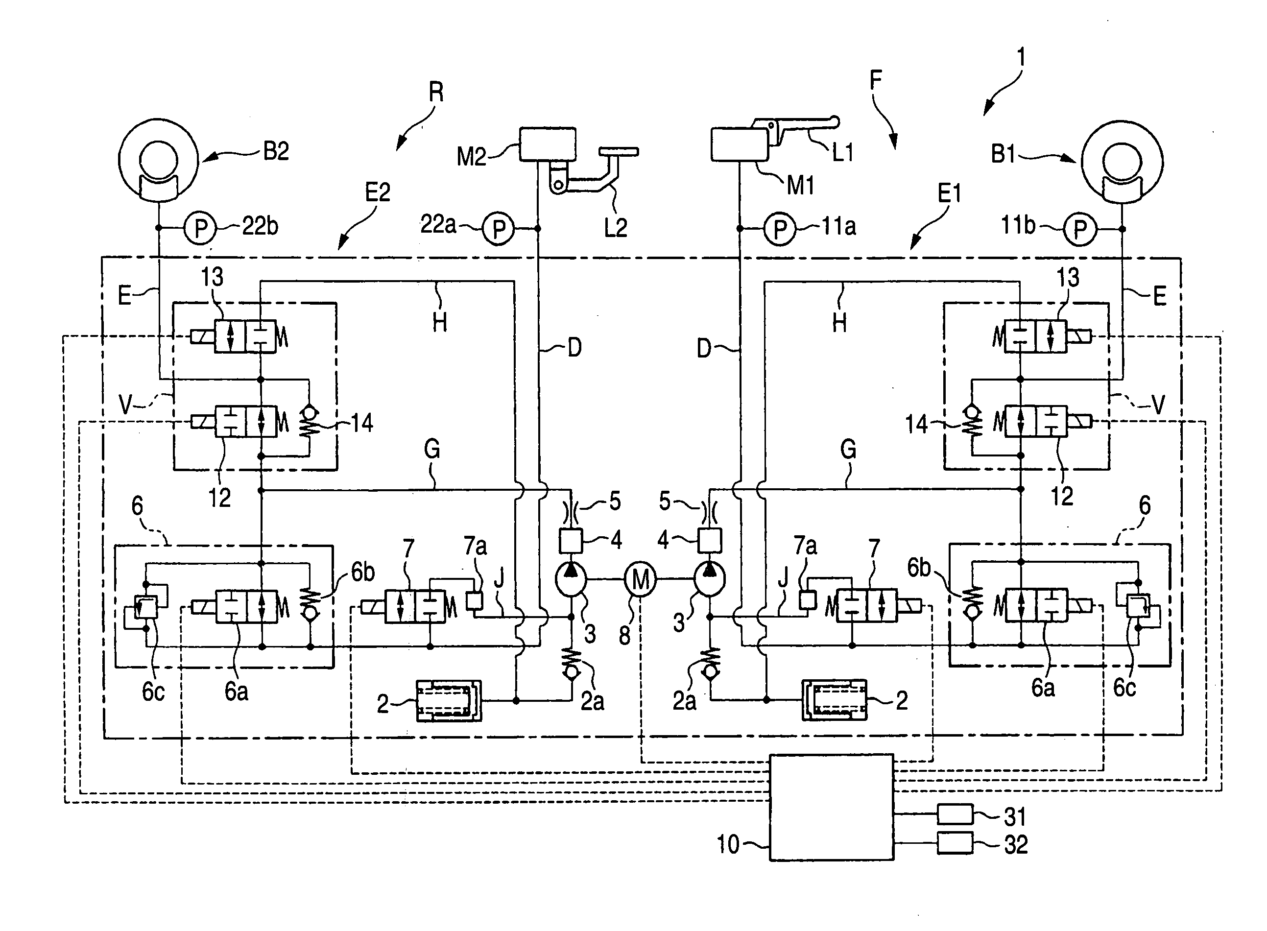
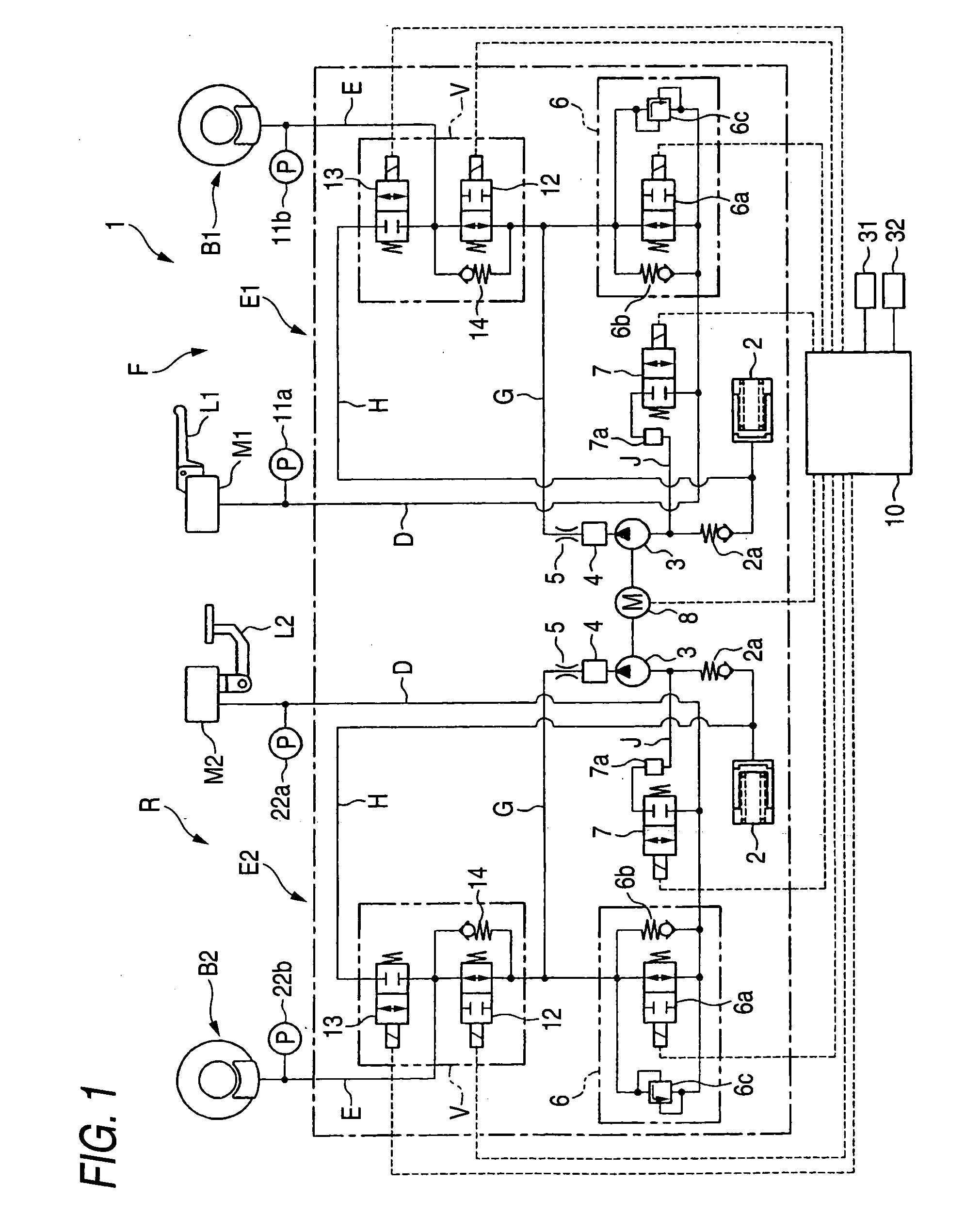
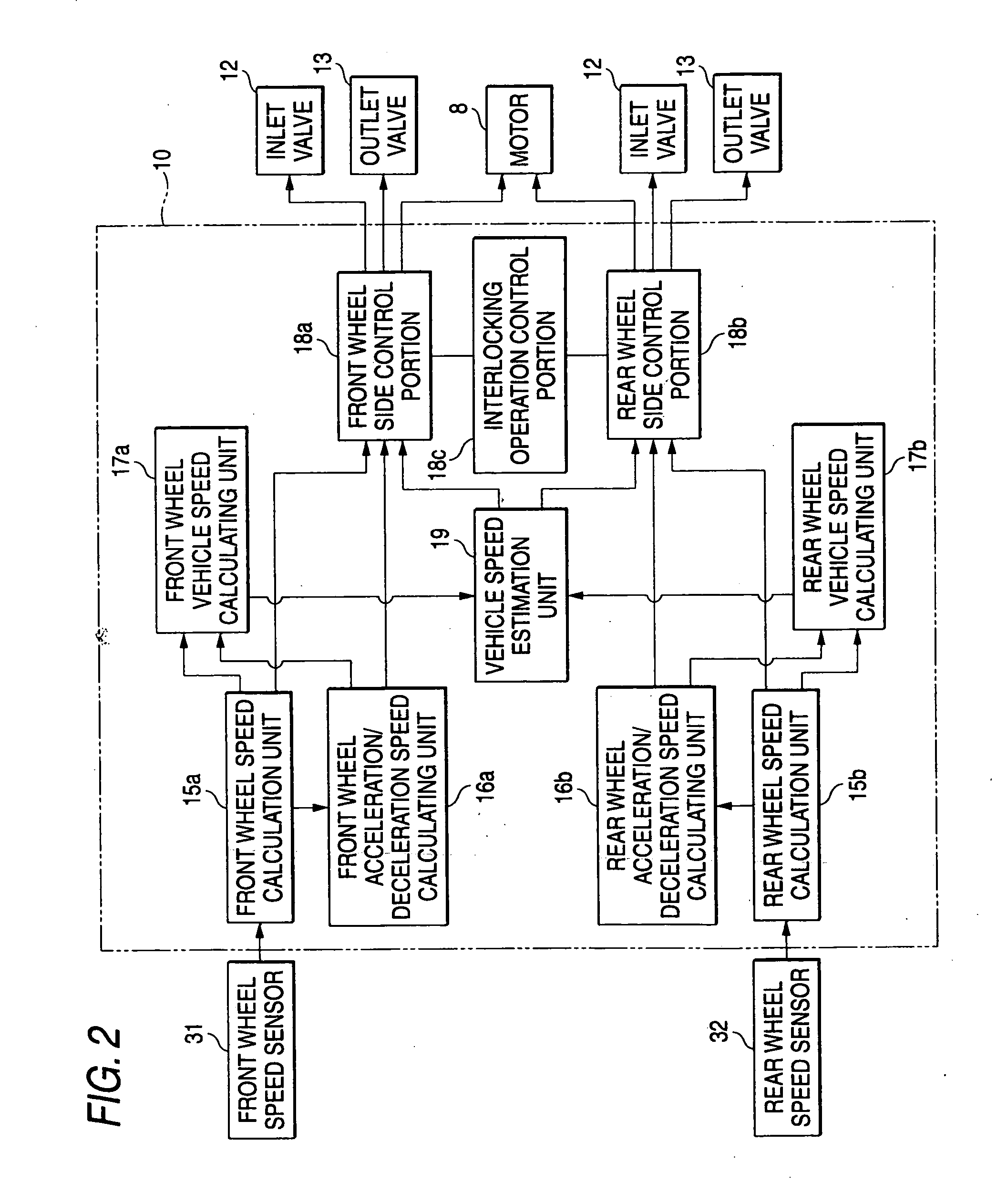
[0055] Hereinafter, the best mode for carrying out the invention will be explained in detail with reference to the accompanying drawings. In the explanation, the same constituent elements are represented by the same signs and the duplicated explanation thereof will be omitted. In the drawings to be referred to, FIG. 1 is a brake fluid pressure circuit diagram showing a vehicular brake control apparatus according to an embodiment of the invention, and FIG. 2 is a block diagram showing the main configuration of the control apparatus.

[0056] A brake control apparatus 1 is suitably used for a vehicle of a bar handle type such as an auto-tricycle, auto-bicycle, or all-terrain vehicle (ATV) and suitably controls a brake force (by means of brake fluid pressure) applied to the front wheel and the rear wheel of a not-shown vehicle. Hereinafter, the explanation will be made as to an example where the brake control apparatus is applied to an auto-bicycle. As shown in FIG. 1, the brake control ...


PUM


Abstract

A control unit 10 controls brake forces of brake systems of a pair of brake operation elements L1, L2 operated independently to perform an anti-lock brake control for eliminating a locked state of a wheel. The control unit 10 applies the brake force to one of the wheel brakes B1, B2 of the brake system which differs from the brake system of the operated brake operation element when the brake operation elements L1, L2 is operated. When one or both of the brake operation elements L1, L2 are operated and so the wheel likely falls in a locked state, the control unit 10 performs an anti-lock brake control on the brake system of the wheel likely falling in the locked state and also performs a brake force application control on the other brake system which is different from the brake system of the wheel likely falling in the locked state.

Description

[0001] The present invention claims foreign priority to Japanese patent applications No. P.2005-076971, filed on Mar. 17, 2005, and No. P.2006-068857, filed on Mar. 14, 2006, the contents of which are incorporated herein by reference. BACKGROUND OF THE INVENTION [0002] 1. Field of the Invention [0003] The present invention relates to a vehicular brake control apparatus and a control method therefor and, in particular, relates to a vehicular brake control apparatus and a control method therefor capable of being mounted mainly on a vehicle of a bar handle type such as an auto-tricycle, auto-bicycle, or all-terrain vehicle (ATV) [0004] 2. Description of the Background Art [0005] Conventionally, there is known a vehicular brake control apparatus capable of operating brakes by electrically controlling brake fluid pressure of the vehicle (see Japanese Patent Unexamined Publications Nos. JP-A-2000-127930 and JP-A-2000-264278, for example). [0006] The vehicular brake control apparatus discl...

Claims


Application Information

Patent Timeline
Patent Type & Authority Applications(United States)
IPC IPC(8): B60T8/34
CPCB60T8/1706B60T8/1766B62L3/08B60T8/3225B60T8/261
Inventor KOYAMA, TOORU
Owner HITACHI ASTEMO LTD
Why Eureka
Try Eureka