Brake control device
A technology of brake control and control equipment, applied in the direction of brakes, etc., can solve problems such as unstable vehicle behavior
- Summary
- Abstract
- Description
- Claims
- Application Information
AI Technical Summary
Problems solved by technology
Method used
Image

Examples
Embodiment 1
[0044] [System Configuration]
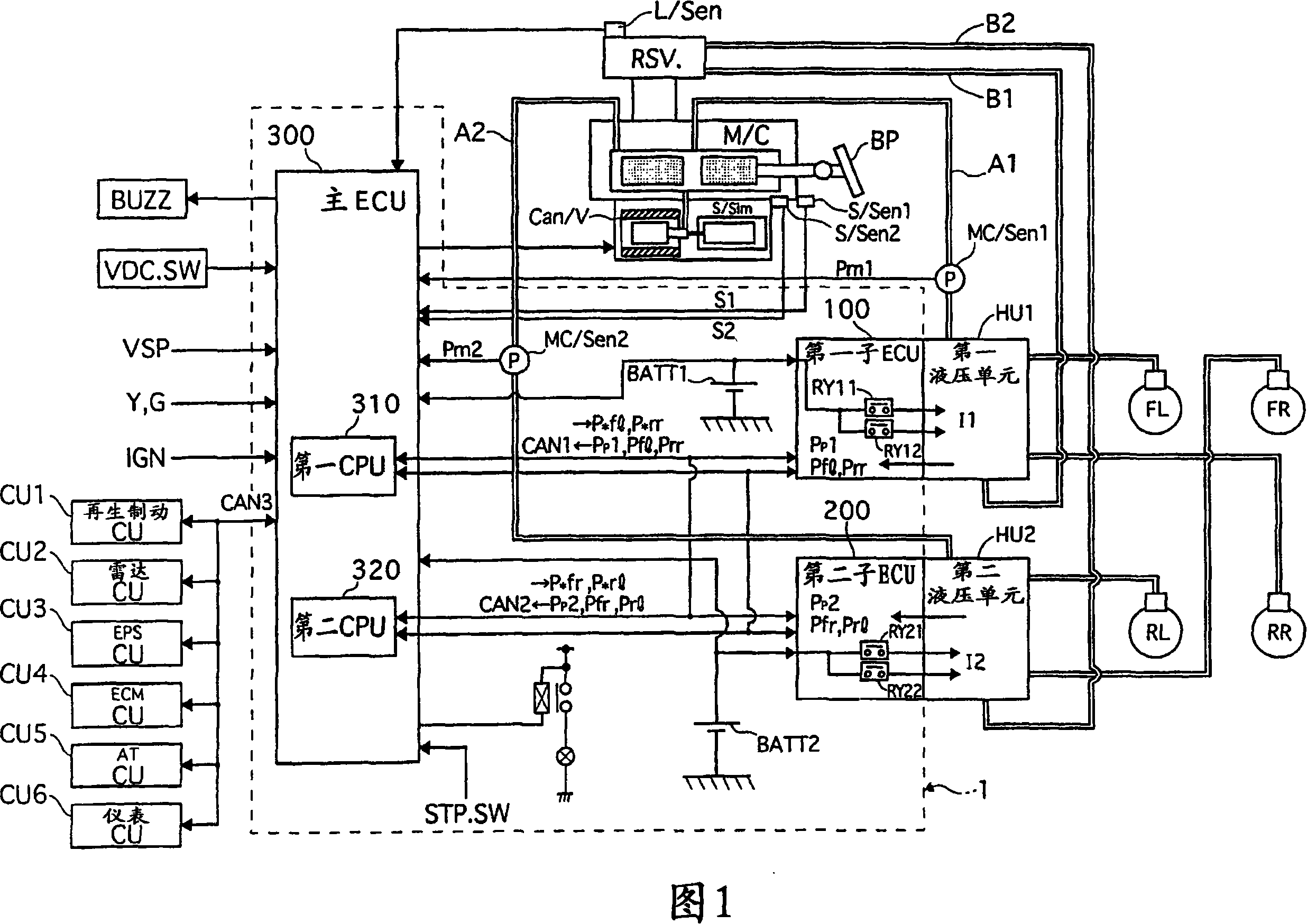
[0045] Embodiment 1 will be described below with reference to FIGS. 1 to 13 . FIG. 1 is a system configuration diagram of a brake control apparatus according to Embodiment 1. FIG. The brake control apparatus according to Embodiment 1 is a four-wheel hydraulic brake-by-wire system including first and second hydraulic pressure units HU1 and HU2 for controlling hydraulic pressure independently of the driver's operation of brake pedal BP.
[0046] The control unit 1 (control mechanism, or control means) includes: a main ECU 300 (main unit) for calculating desired wheel cylinder pressures P*fl to P*rr of the wheels FL to RR; and sub-ECUs 100 and 200 ( first and second subunits) for driving the first and second hydraulic units HU1 and HU2.
[0047] The first and second hydraulic pressure units HU1 and HU2 are driven by the first and second sub-ECUs 100 and 200 according to commands from the main ECU 300 . Stroke simulator S / Sim connected to master ...
Embodiment 2
[0248] Embodiment 2 will be described below with reference to FIGS. 14 to 16 . Since the basic configuration is similar to that of Embodiment 1, only the different points will be described below. In Embodiment 1, during supercharging, the difference in fluid pressure between the left and right wheels is corrected by reducing the output of the motor connected to the higher pressure wheel cylinders of the left and right wheels. In contrast, in Embodiment 2, the difference in fluid pressure is corrected by increasing the output of the motor connected to the lower pressure wheel cylinder.
[0249] [Relationship of commands between ECUs]
[0250] (Control to increase the motor output of the lower pressure unit during boosting)
[0251] 14 is a block diagram showing the relationship of commands between the main ECU 300, the first and second sub-ECUs 100 and 200 under braking force correction control (control to increase the motor output of the lower pressure unit).
[0252] The m...
Embodiment 3
[0285] [Control to reduce the flow rate of the higher pressure intake valve during boosting]
[0286] Embodiment 3 will be described below with reference to FIGS. 17 to 19 . The basic configuration of this embodiment is similar to that in Embodiment 1. In Embodiment 1, braking force correction is performed by reducing the output of the motor connected to the higher pressure wheel cylinders in the left and right wheels. In contrast, in Embodiment 3, the braking force correction is performed by reducing the opening degree of the intake valve IN / V connected to the higher pressure wheel cylinder so as to reduce the flow of the intake valve IN / V(FL). Rate.
[0287] For example, when the FL wheel actual wheel cylinder pressure Pfl is higher than the FR wheel actual wheel cylinder pressure Pfr based on a single desired wheel cylinder pressure P*α, the FL wheel intake valve IN / V(FL) (which is normally solenoid valve) to be smaller than that of the FR wheel intake valve IN / V (FR), t...
PUM
 Abstract
Description
Claims
Application Information
 - Generate Ideas
- Intellectual Property
- Life Sciences
- Materials
- Tech Scout
- Unparalleled Data Quality
- Higher Quality Content
- 60% Fewer Hallucinations
Browse by: Latest US Patents, China's latest patents, Technical Efficacy Thesaurus, Application Domain, Technology Topic, Popular Technical Reports.
© 2025 PatSnap. All rights reserved.Legal|Privacy policy|Modern Slavery Act Transparency Statement|Sitemap|About US| Contact US: help@patsnap.com