
Braking force control system

a technology of control system and brake force, applied in the direction of brake control system, brake system, vehicle components, etc., can solve problems such as unstable behavior of vehicles, and achieve the effect of stable behavior

Active Publication Date: 2017-07-18
HONDA MOTOR CO LTD
View PDF14 Cites 7 Cited by
  • Summary
  • Abstract
  • Description
  • Claims
  • Application Information

AI Technical Summary

Benefits of technology

The patent text is about a braking force control system that helps vehicles have better behavior. The technical effect is that this system helps to make vehicles more stable and secure.

Problems solved by technology

However, for braking a vehicle having the front and rear wheels, if the rear wheels are locked ahead of the front wheels, the vehicle may have unstable behavior.

Method used


Image

  • Braking force control system
  • Braking force control system
  • Braking force control system

Examples


first embodiment

[0042]Hereinafter, embodiments of the present invention will be described with reference to accompanying drawings.

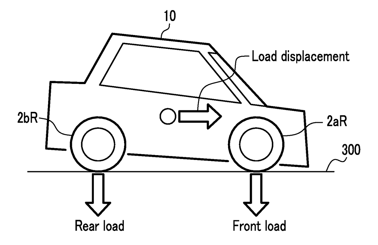
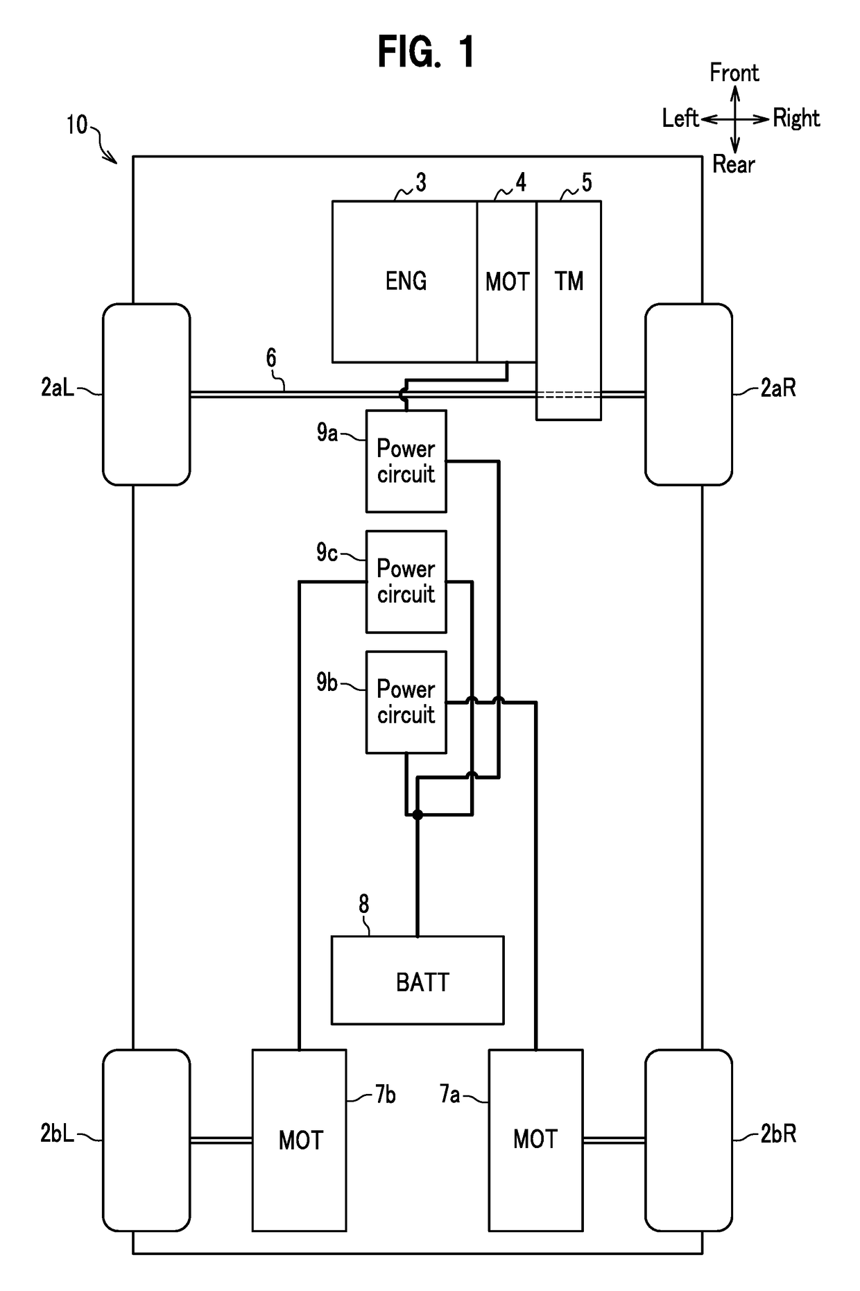
[0043]FIG. 1 is a system diagram of main parts of a vehicle 10 in a first embodiment of the present invention. The vehicle 10 is, for example, a hybrid vehicle of four-wheel drive, including a pair of right and left front wheels 2aR, 2aL arranged on a front side of the vehicle 10 and a pair of right and left rear wheels 2br, 2bL arranged on a rear side of the vehicle 10.

[0044]The vehicle 10 is, for example, a parallel hybrid vehicle which includes an engine 3, a front-wheel motor-generator 4 (second motor-generator), and a transmission 5, all being connected such as in series, and driving forces of the engine 3 and the front-wheel motor-generator 4 are distributed and transmitted to the right and left front wheels 2aR, 2aL arranged on an axle 6 via the transmission 5 and a differential (not shown). The front wheels 2aR, 2aL of the vehicle 10 may be driven only by the eng...

second embodiment

[0108]FIG. 8 is a schematic diagram of a configuration of a vehicle including a braking force control system of the present embodiment.

[0109]As shown in FIG. 8, a vehicle 301 of the present embodiment is a four-wheel drive vehicle having two front wheels FW and two rear wheels RW. The vehicle 301 is assumed to have a front on a side where the front wheels FW are provided and a rear on a side where the rear wheels RW are provided. In addition, a right and a left are set for the vehicle 301 as viewed from the rear.

[0110]The front wheels FW are driven by driving forces generated by an engine 310 and a front-wheel motor-generator 311 (second motor-generator). The front wheels FW are configured to have a hybrid drive by the driving forces of the engine 310 and the front-wheel motor-generator 311. The rear wheels RW are driven by a driving force generated by a rear-wheel motor-generator 312 (first motor-generator). The engine 310 is controlled by an engine ECU 310a (braking force determin...


PUM


Abstract

Motor-generators are arranged both at front and rear wheels so as to be capable of using all of four wheels for regeneration. The horizontal axis indicates deceleration of a vehicle, and the vertical axis indicates braking forces for the front and rear wheels, respectively above and below the horizontal axis. A setting value indicates a limit braking force for the rear wheels to be locked. A frictional braking force and a regenerative braking force at the rear wheels are controlled so that the total braking force for the rear wheels does not exceed the setting value.

Description

CROSS REFERENCE TO RELATED APPLICATIONS[0001]This application is a U.S. National Stage Application under 35 U.S.C. §371 of International Patent Application No. PCT / JP2014 / 079575 filed 7 Nov. 2014, which claims the benefit of priority to Japanese Patent Application No. 2013-232114 filed 8 Nov. 2013 and Japanese Patent Application No. 2013-232549 filed 8 Nov. 2013, the disclosures of all of which are hereby incorporated by reference in their entireties.TECHNICAL FIELD[0002]The present invention relates to a braking force control system.BACKGROUND ART[0003]The Japanese Patent Application Publication No. 2004-268901 discloses a technique of distributing engine brake torque to front wheels and rear wheels in accordance with an ideal braking-torque distribution in a four-wheel drive vehicle which drives front wheels by an engine and rear wheels by a motor for suppressing either the front wheels or the rear wheels from being locked.SUMMARY OF THE INVENTIONProblems to be Solved[0004]However...

Claims


Application Information

Patent Timeline
Patent Type & Authority Patents(United States)
IPC IPC(8): B60T8/1766B60T8/26B60T8/40
CPCB60T8/1766B60T8/267B60T8/4081B60T2270/602B60T2270/604
Inventor DOI, SHIGERUSHIMODA, AKIOYANAGIDA, HISANORI
Owner HONDA MOTOR CO LTD
Learn More