
Thin printable electrochemical cell utilizing a "picture frame" and methods of making the same

a printing and electrochemical cell technology, applied in the field of electrochemical cells or batteries, can solve the problems of not being able and being unable to meet the needs of new thin low cost batteries

Active Publication Date: 2006-09-28
BLUE SPARK INNOVATIONS LLC
View PDF99 Cites 94 Cited by
  • Summary
  • Abstract
  • Description
  • Claims
  • Application Information

AI Technical Summary

Benefits of technology

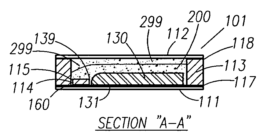
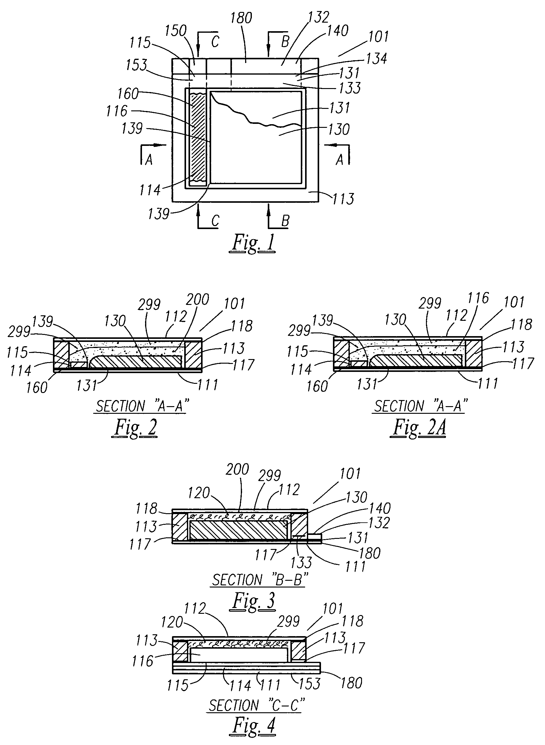
[0008] Provided are a plurality of embodiments of a device including one or more electrochemical cells acting as a battery power source. These embodiments include, but are not limited to a device comprising an electrochemical cell for generating an electrical current, with the cell of this device including a first substrate layer of a substantially uniform thickness and a second substrate layer of a substantially uniform thickness. Also included is a cathode layer provi

Problems solved by technology

In the early days of portable power, these power sources were very large compared to today's standards.
This high cost battery with multiple layers and a metal foil laminate package is a high voltage, high current battery, capable of igniting flash bulbs and powering motors, for example, and is not a realistic competitor of the new thin low cost batteries that are needed.
Furthermore, a previously described construction in an earlier application, which is assembled using a horizontal pouch filler, (see application Ser. No. 11 / 110,202, incorporated by reference), may lead to some possible air entrapment, and thus might not be as flat and thin as might be desirable for some applications.
Also, such cells disclosed therein may be vulnerable to large compression forces.
In addition, it would be useful to avoid the need for the paper layer disclosed in the construction of some embodiments of that application, and furthermore, the liquid electrolyte of that application could prove difficult to handle and may not be printable.

Method used


Image

  • Thin printable electrochemical cell utilizing a "picture frame" and methods of making the same
  • Thin printable electrochemical cell utilizing a "picture frame" and methods of making the same
  • Thin printable electrochemical cell utilizing a "picture frame" and methods of making the same

Examples


Embodiment Construction

[0044] As used herein, unless otherwise explicitly indicated, all percentages are percentages by weight. Also, as used herein, when a range such as “5-25” (or “about 5-25”) is given, this means, for at least one embodiment, at least about 5 and, separately and independently, not more than about 25, and unless otherwise indicated, ranges are not to be strictly construed, but are given as acceptable examples. Also herein, a parenthetical range following a listed or preferred value indicates a broader range for that value according to additional embodiments of the invention.

[0045] The present invention relates to thin, printed electrochemical cells and / or batteries comprising a plurality of such cells. Such cells each typically include at least a first electrode including a first electrochemical layer (e.g., a cathode), a second electrode including a second electrochemical layer (e.g., an anode), and an electrolyte that interacts with the electrodes to create an electrical current. Al...


PUM

PropertyMeasurementUnit
Thicknessaaaaaaaaaa
Dielectric polarization enthalpyaaaaaaaaaa
Viscosityaaaaaaaaaa

Abstract

A thin printed flexible electrochemical cell, and its method of manufacture, using a “picture frame” structure sealed, for example, with a high moisture and oxygen barrier polymer film and featuring, for example, a printed cathode deposited on an optional, highly conductive carbon printed cathode collector with a printed or a foil strip anode placed adjacent to the cathode. A viscous or gelled electrolyte is dispensed and / or printed in the cell, and a top laminate can then be sealed onto the picture frame. Such a construction could allow the entire cell to be made on a printing press, for example, as well as gives the opportunity to integrate the battery directly with an electronic application, for example.

Description

CROSS-REFERENCESS TO RELATED APPLICATIONS [0001] This application claims the benefit of provisional applications Ser. Nos. 60 / 664,135, filed on Mar. 22, 2005; 60 / 678,726 filed on May 6, 2005; and 60 / 760,242 filed on Jan. 19, 2006; each of which is incorporated herein by reference in their entirety.BACKGROUND OF THE INVENTION [0002] This application relates generally to an electrochemical cell or battery, and more specifically relates to a flat, thin, electrochemical cell utilizing a picture frame feature and its method of manufacture, including printing methods. Even more specifically, this invention relates to a thin printable cell comprising two electrodes, a separator, electrolyte, and a cell frame between two laminated film layers, and its method of manufacture. [0003] For the past one hundred years or so, scientists have been making Carbon / Zinc portable power sources for various applications. In the early days of portable power, these power sources were very large compared to t...

Claims


Application Information

Patent Timeline
IPC IPC(8): H01M2/02H01M2/08H01M2/16H01M4/50H01M50/105H01M50/119H01M50/121H01M50/126H01M50/133H01M50/186H01M50/193H01M50/211
CPCH01M2/0207Y10T29/49115H01M2/0275H01M2/06H01M2/08H01M2/10H01M2/1061H01M2/1094H01M2/16H01M2/1686H01M2/18H01M4/42H01M4/50H01M4/663H01M4/667H01M6/40H01M6/42H01M6/46H01M10/0436H01M10/365H01M10/425H01M12/085H01M2300/0085Y10T29/49108H01M2/021Y02E60/10H01M50/124H01M50/24Y02P70/50H01M50/105H01M50/121H01M50/186H01M50/193H01M50/211H01M50/126H01M50/133H01M50/119H01M10/0585H01M50/178H01M10/0565H01M2300/0002
Inventor TUCHOLSKI, GARY R.
Owner BLUE SPARK INNOVATIONS LLC
Learn More