
Neighbor location discovery with directional antennas in a mesh network

a mesh network and directional antenna technology, applied in the field of computer networks, can solve the problems of power drain on the node, low network performance, and high complexity of the antenna, and achieve the effect of convenient implementation and convenient availability

Active Publication Date: 2006-09-28
ZHIGU HLDG
View PDF11 Cites 49 Cited by
  • Summary
  • Abstract
  • Description
  • Claims
  • Application Information

AI Technical Summary

Benefits of technology

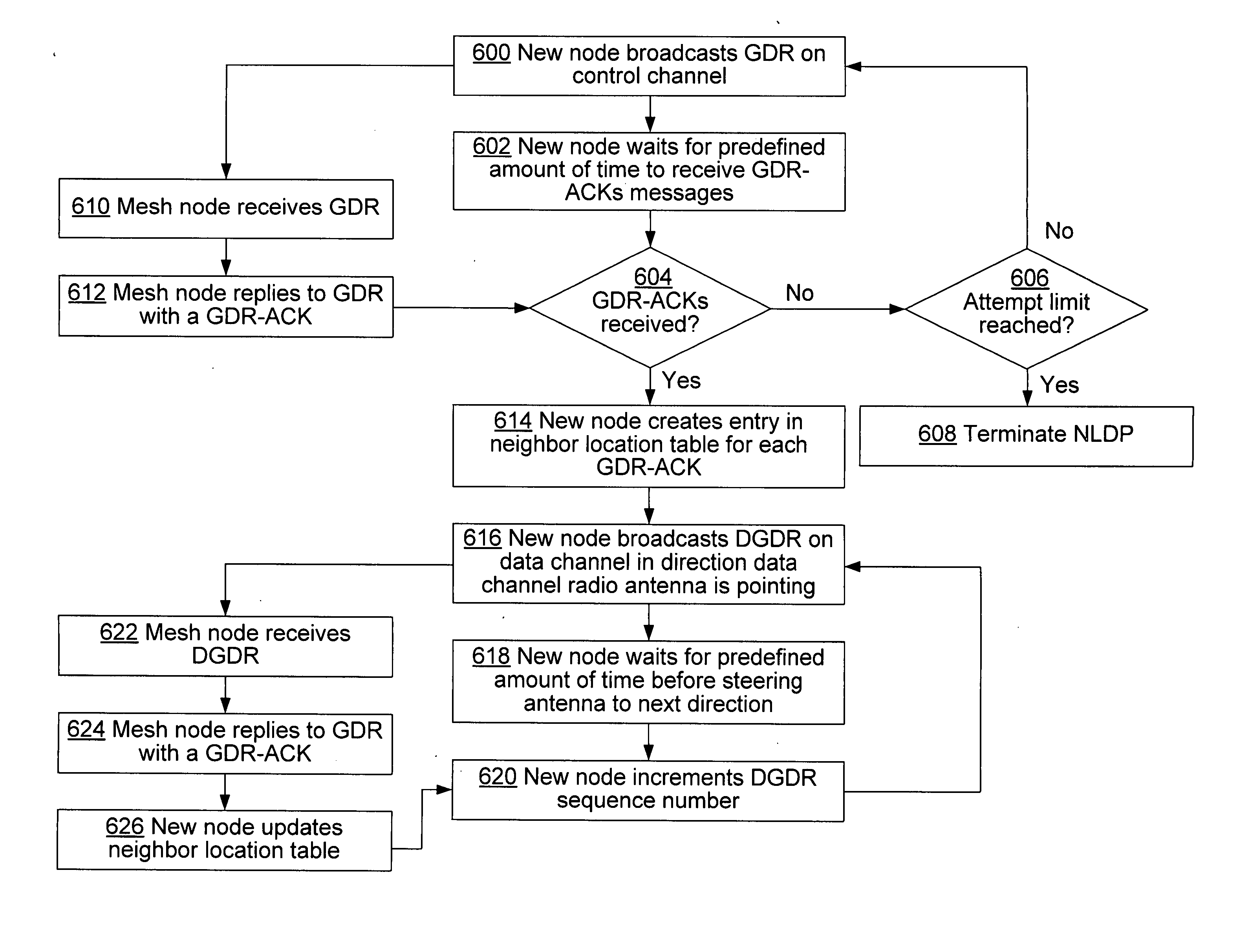
"The present invention provides a Neighbor Location Discovery Protocol (NLDP) for determining the relative location of nodes in a mesh network, particularly in an ad-hoc wireless network where the nodes are equipped with directional antennas and not able to use GPS. The NLDP offers advantages over previous protocols due to the difference in hardware configuration of the router nodes. It exploits the host node's ability to operate simultaneously over non-overlapping channels to quickly converge on the neighbor's location. Multiple transceivers offer the possibility of informing \"future\" destination nodes to point their directional antenna at the sender, even while the sender and the future destination node are pointing their antennas in different directions and are engaged in communication with other nodes. The NLDP is limited by the range of the control channel, but this can be increased to match or exceed the range on the data channel when properly aimed directional antennas are used by both the transmitter and the receiver. Additional transceivers can cause power drain on the node, but this is not an issue in scenarios such as the community networking scenario, where battery capacity is not an issue."

Problems solved by technology

A tradeoff exists between antenna complexity, speed of convergence, and number of transceivers.
As a final consideration, additional transceivers can cause power drain on the node, however in scenarios such as the community networking scenario, battery capacity is not and issue.

Method used


Image

  • Neighbor location discovery with directional antennas in a mesh network
  • Neighbor location discovery with directional antennas in a mesh network
  • Neighbor location discovery with directional antennas in a mesh network

Examples


Embodiment Construction

[0027] In the description that follows, the invention is described with reference to acts and symbolic representations of operations that are performed by one or more computing devices, unless indicated otherwise. As such, it will be understood that such acts and operations, which are at times referred to as being computer-executed, include the manipulation by the processing unit of the computing device of electrical signals representing data in a structured form. This manipulation transforms the data or maintains them at locations in the memory system of the computing device, which reconfigures or otherwise alters the operation of the computing device in a manner well understood by those skilled in the art. The data structures where data are maintained are physical locations of the memory that have particular properties defined by the format of the data. However, while the invention is being described in the foregoing context, it is not meant to be limiting as those of skill in the...


PUM


Abstract

Disclosed is a Neighbor Location Discovery Protocol (NLDP) that determines the relative locations of the nodes in a mesh network. In one embodiment, NLDP can be implemented for an ad-hoc wireless network where the nodes are equipped with directional antennas and are not able to use GPS. While NLDP relies on nodes having at least two RF transceivers, it offers significant advantages over previously proposed protocols that employ only one RF transceiver. In NLDP antenna hardware is simple, easy to implement, and readily available. Further, NLDP exploits the host node's ability to operate simultaneously over non-overlapping channels to quickly converge on the neighbor's location. NLDP is limited by the range of the control channel, which operates in a omni-directional fashion. However, by choosing a low frequency band, high power, and low data rate, the range of the control channel can be increased to match the range on the data channel.

Description

TECHNICAL FIELD [0001] The present invention relates generally to computer networks and, more particularly, to multi-hop wireless mesh networks. BACKGROUND OF THE INVENTION [0002] Multi-hop wireless networks have been the subject of much study over the past decade. Much of the original work was motivated by military applications such as battlefield communications. More recently, however, some interesting commercial applications have emerged which has led to a surge of interest in building wireless neighborhood, or mesh, networks. One example is “community wireless mesh networks”, where a multi-hop wireless network, perhaps based on the IEEE 802.11 standard, is used to provide “last-milebroadband Internet access to peoples' homes. [0003] There are several advantages to enabling such connectivity. For example, when enough neighbors cooperate and forward each others packets, they do not need to individually install dedicated wired Internet connections, but instead can share faster, m...

Claims


Application Information

Patent Timeline
Patent Type & Authority Applications(United States)
IPC IPC(8): H04L12/26H04Q7/24H04W8/00H04W84/18
CPCH04W8/005H04W84/18
Inventor ADYA, ATULBAHL, PARAMVIRPADHYE, JITENDRA D.WOLMAN, ALASTAIR
Owner ZHIGU HLDG
Learn More