
Electron temperature measurement method, electron temperature measurement program for implementing the method, and storage medium storing the electron temperature measurement program

a technology of electron temperature and measurement method, which is applied in the direction of plasma technique, electric discharge lamp, coating, etc., can solve the problems of insufficient method, unstable and imprecise measurement of electron temperature, and inability to read plasma parameters directly

Inactive Publication Date: 2006-09-28
TOKYO ELECTRON LTD
View PDF0 Cites 15 Cited by
  • Summary
  • Abstract
  • Description
  • Claims
  • Application Information

AI Technical Summary

Benefits of technology

[0011] It is an object of the present invention to provide an electron temperature measurement method, an electron temperature measurement program for implementing the method, and a storage medium storing the electron temperature measurement program, that enable the as a plasma parameter to be measured precisely.
[0013] According to the construction of the first aspect as described above, the ion energy distribution in the vacuum processing chamber is measured, the ion energy distribution in the vacuum processing chamber is simulated based on a set electron temperature, the measured ion energy distribution and the simulated ion energy distribution are compared, and the electron temperature of the plasma is estimated based on the results of the comparison. There is a correlation between the ion energy distribution in the vacuum processing chamber and the electron temperature. Moreover, the ion energy distribution can be measured precisely, and furthermore if the electron temperature is set to a predetermined value then the ion energy distribution can be simulated. Consequently, in the case that the measured ion energy distribution and the simulated ion energy distribution are the same as or closely approximate one another, if the electron temperature used in the ion energy distribution simulation is estimated as being the electron temperature of the plasma in the vacuum processing chamber, then the electron temperature as a plasma parameter can be measured precisely.
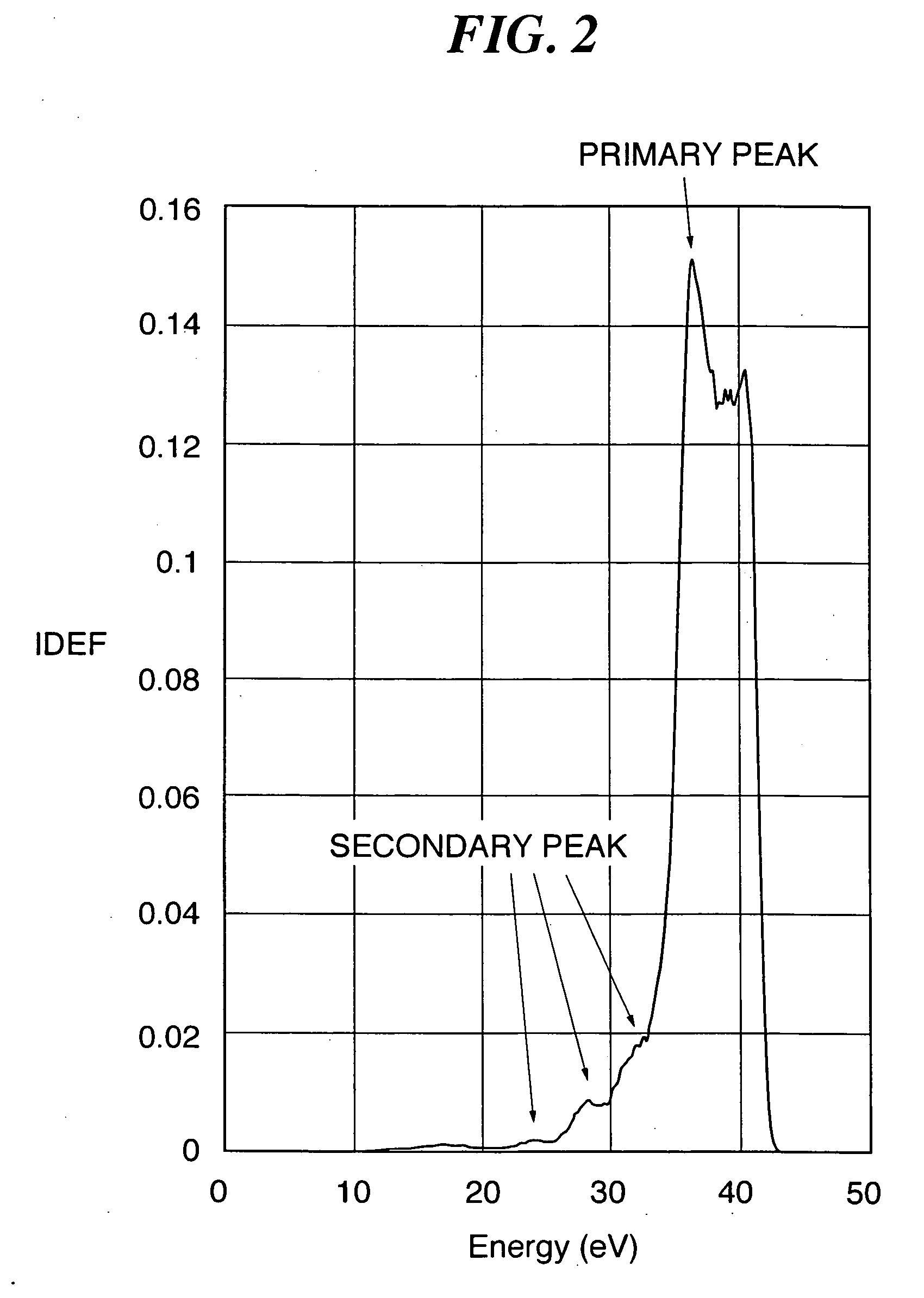
[0016] According to the construction of the second aspect as described above, in the comparison between the measured ion energy distribution and the simulated ion energy distribution, the energy value at which a secondary peak arises in the measured ion energy distribution and the energy value at which a corresponding secondary peak arises in the simulated ion energy distribution are compared. There is a strong correlation between the energy values at which the secondary peaks arise in the ion energy distribution and the electron temperature. Consequently, by comparing the energy values at which a secondary peak arises, the electron temperature as a plasma parameter can be measured more precisely.
[0018] According to the construction of the second aspect as described above, the electron temperature used in the ion energy distribution simulation is tentatively set to a predetermined value. As a result, the number of times that the ion energy distribution simulation is repeated in accordance with the results of the comparison between the measured ion energy distribution and the simulated ion energy distribution can be reduced, and hence the electron temperature as a plasma parameter can be measured quickly.
[0020] According to the construction of the second aspect as described above, the plasma density and the sheath potential are estimated based on the results of the comparison between the measured ion energy distribution and the simulated ion energy distribution. There is a correlation between the ion energy distribution in the vacuum processing chamber and the plasma density and sheath potential. Moreover, if the plasma density and sheath potential are each set to a predetermined value then the ion energy distribution can be simulated. Consequently, in the case that the measured ion energy distribution and the simulated ion energy distribution are the same as or closely approximate one another, if the plasma density and sheath potential used in the ion energy distribution simulation are estimated as being the plasma density and sheath potential in the vacuum processing chamber, then the plasma density and the sheath potential as plasma parameters can be measured precisely.
[0022] According to the construction of the second aspect as described above, in the comparison between the measured ion energy distribution and the simulated ion energy distribution, the energy value at which a primary peak arises in the measured ion energy distribution and the energy value at which a primary peak arises in the simulated ion energy distribution are compared. There is a strong correlation between the energy value at which the primary peak arises in the ion energy distribution and the plasma density and sheath potential. Consequently, by comparing the energy values at which the primary peak arises, the plasma density and sheath potential as plasma parameters can be measured more precisely.

Problems solved by technology

In the Langmuir probe method, it is necessary to determine and then analyze the voltage-current characteristic, and hence the method is not suitable for reading the plasma parameters directly.
However, none of the above methods have been adequate as a method of measuring the electron temperature as a plasma parameter.
For example, with the Langmuir probe method or the direct plasma parameter reading method, the measurement cannot follow rapid changes over time in the potential in the chamber caused by the application of radio frequency electrical power for producing the plasma, and hence the measured electron temperature is unstable and imprecise.
Moreover, with the plasma absorption probe method, only the plasma density can be measured; the electron temperature cannot be measured.

Method used


Image

  • Electron temperature measurement method, electron temperature measurement program for implementing the method, and storage medium storing the electron temperature measurement program
  • Electron temperature measurement method, electron temperature measurement program for implementing the method, and storage medium storing the electron temperature measurement program
  • Electron temperature measurement method, electron temperature measurement program for implementing the method, and storage medium storing the electron temperature measurement program

Examples


Embodiment Construction

[0034] The present invention will now be described in detail with reference to the drawings showing preferred embodiments thereof.

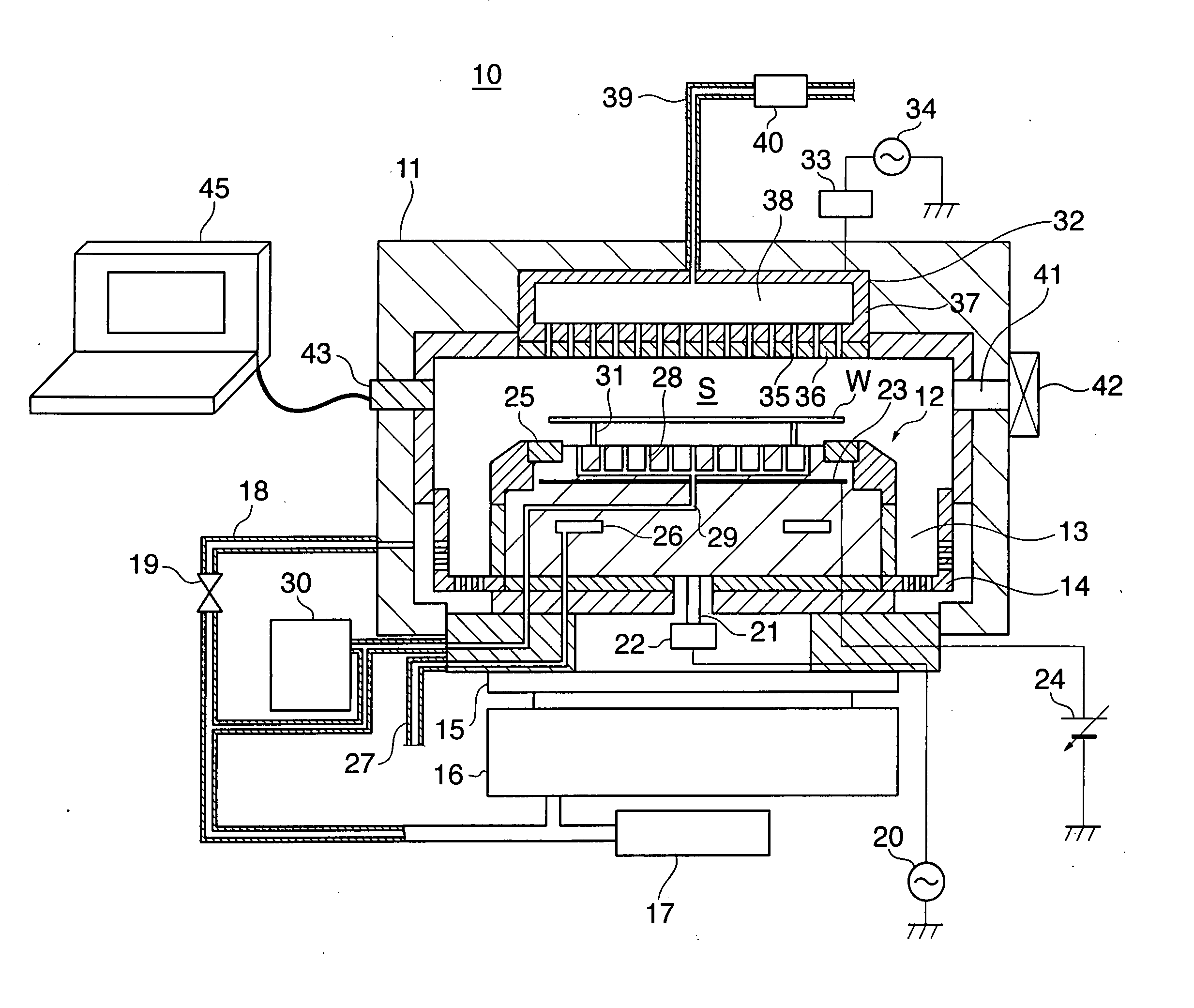
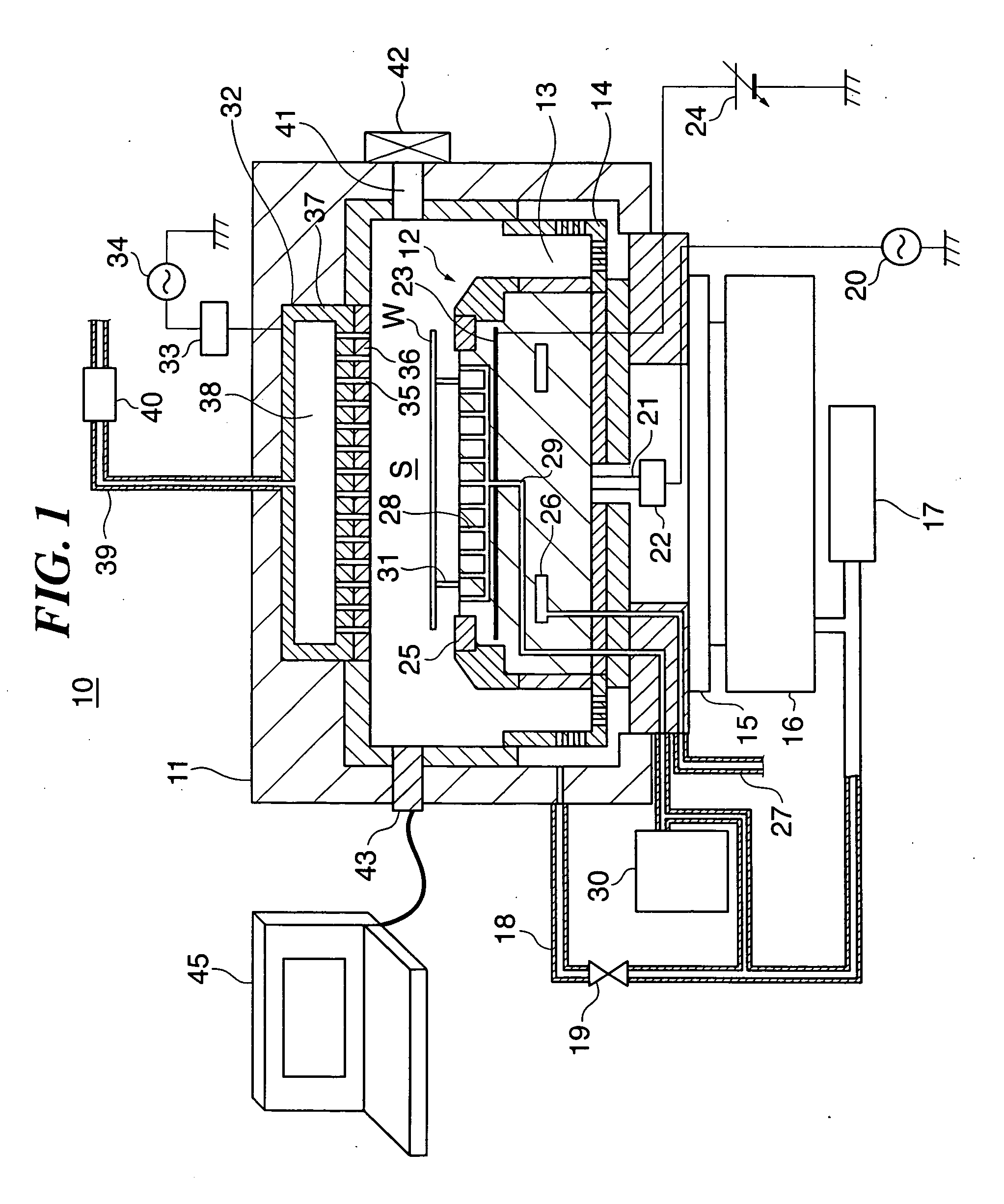
[0035]FIG. 1 is a sectional view schematically showing the construction of a parallel plate type plasma processing apparatus to which is applied an electron temperature measurement method according to an embodiment of the present invention.

[0036] As shown in FIG. 1, the plasma processing apparatus 10, which subjects semiconductor device wafers (hereinafter referred to merely as “wafers”) W to dry etching (reactive ion etching) (hereinafter referred to as “RIE”) as desired plasma processing, has a cylindrical chamber 11 (vacuum processing chamber) made of metal such as aluminum or stainless steel. A cylindrical susceptor 12 is disposed in the chamber 11 as a stage on which is mounted a wafer W having a diameter of, for example, 300 mm.

[0037] In the plasma processing apparatus 10, an exhaust path 13 that acts as a flow path through which gas molecules ab...


PUM

PropertyMeasurementUnit
ion energy distribution simulationaaaaaaaaaa

Abstract

An electron temperature measurement method that enables an electron temperature as a plasma parameter to be measured precisely. A plasma is produced in a chamber 11 such that a wafer W is subjected to reactive ion etching therein. An ion energy distribution in the chamber 11 is measured. An ion energy distribution in the chamber 11 is simulated based on a set electron temperature. The measured ion energy distribution and the simulated ion energy distribution are compared. The electron temperature of the plasma is estimated based on results of the comparison mentioned above.

Description

BACKGROUND OF THE INVENTION [0001] 1. Field of the Invention [0002] The present invention relates to an electron temperature measurement method, an electron temperature measurement program for implementing the method, and a storage medium storing the electron temperature measurement program. [0003] 2. Description of the Related Art [0004] In recent years, as etching carried out on wafers (substrates) in a vacuum processing chamber (hereinafter merely referred to as the “chamber”) has been made finer and metallic films formed on such wafers in such a chamber have been made thinner, it has become required to precisely measure the state of plasma in the chamber, in particular plasma parameters. [0005] A commonly known method of measuring such plasma parameters in such a chamber is a so-called Langmuir probe method in which a probe that has been given electrical potential is directly inserted into the chamber, and plasma parameters such as the plasma density, the electron temperature of...

Claims


Application Information

Patent Timeline
Patent Type & Authority Applications(United States)
IPC IPC(8): H01J7/24
CPCH01J37/32935H05H1/0081
Inventor DENPOH, KAZUKI
Owner TOKYO ELECTRON LTD
Learn More