Apparatus for and method of manufacturing an optical disc

a technology of optical discs and apparatuses, applied in the direction of dough shaping, manufacturing tools, applications, etc., can solve the problems of high accuracy, high application requirements, and damage to not only the stamper, but also the spacer layer or the substra

Inactive Publication Date: 2006-09-28
TDK CORPARATION
View PDF7 Cites 2 Cited by
  • Summary
  • Abstract
  • Description
  • Claims
  • Application Information

AI Technical Summary

Benefits of technology

[0010] The present invention has been made in view of the above-described situation, and has as an object thereof to provide an apparatus for and a method of stripping off a stamper, i.e., an apparatus for and a method of manufacturing an optical disc, which, even when use is made of a tin stamper having a thickness of e.g. 0.6 mm, are free of or reduced in the possibility of damaging the stamper and a spacer layer.
[0014] According to the present invention, it becomes possible to sequentially continuously shift a position at which a load is applied to the stamper during stripping-off to a position which can effectively act on the stripping-off with the progress of the stripping-off. Therefore, unlike a case where a pin or the like is used, it is eliminated for a load to concentrate on a localized portion of the stamper in a state in which the action on the stripping-off has been reduced (at a position whereat contribution to the actual stripping-off is low), and the excessive concentration of the load to the stamper is prevented. Therefore, it becomes possible to execute the stripping-off step without giving damage or the like even to a thinner stamper. Also, the contact point between the stamper and a stripping-off jig is obtained by a roller rolling along the surface of the stamper so that it may become possible to effect the movement of this contact point with low friction. Accordingly, as compared with the case where the pin or the like is used, it becomes possible to reduce a frictional force at the contact point, and it also becomes possible to reduce the stripping-off load due to this frictional force.
[0015] Also, according to the present invention, the operations is the apparatus which become necessary with the stripping-off operation are only the operation of rotating the rotary table, the operation of moving up and down the thrusting-up roller, and the operation of retracting the stripping-off arm, and as compared with the construction shown in Japanese Patent Application No. 2003-326535 A, it becomes possible to reduce the number of constituents. Also, many of the constituents are simple in operation itself, and it also becomes possible to constitute a driving system by a simple driving device. Accordingly, it becomes easy to stabilize the stripping-off operation, and it is also easy to downsize the apparatus itself. Also, it is possible to continuously move the above-mentioned contact point (thrust-up point) and therefore, even if the speed of the stripping-off operation is increased, it does not lead to a great increase in the load to the stamper, and there is also obtained the effect of shortening the working time.

Problems solved by technology

In this method, however, there is the possibility of damaging not only the stamper, but also the spacer layer or the substrate, and in case of stripping-off, the application of a very great force has been required.
Thus, the stamper used for the transferring of the groove has a groove pattern which is minute and high in accuracy of formation, and the cost required for the working of the stamper itself is rising.
However, when the stripping-off of the stamper is effected by pushing up the vicinity of the outer periphery of the stamper from the surface of the substrate by the pins, the concentration of a load occurs to the contact portion between the pins and the stamper.
Also, the frictional force between the tip ends of the pins and the contact surface of the stamper occurring to the contact portion is great.
Therefore, there remains the possibility of damaging the stamper.
Also, when the stamper is made into a thin layer having a thickness of e.g. 0.6 mm, there is the undesirable possibility that such a construction cannot cope with the thin-layer stamper.

Method used


Image

  • Apparatus for and method of manufacturing an optical disc
  • Apparatus for and method of manufacturing an optical disc
  • Apparatus for and method of manufacturing an optical disc

Examples


Embodiment Construction

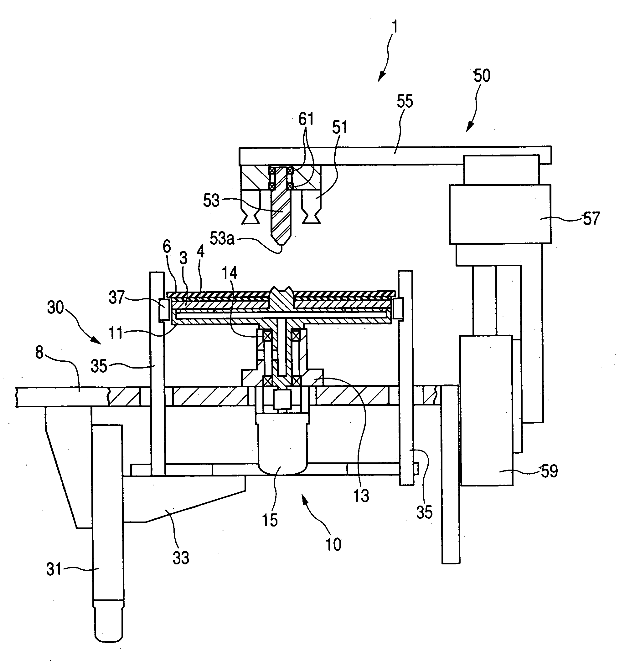
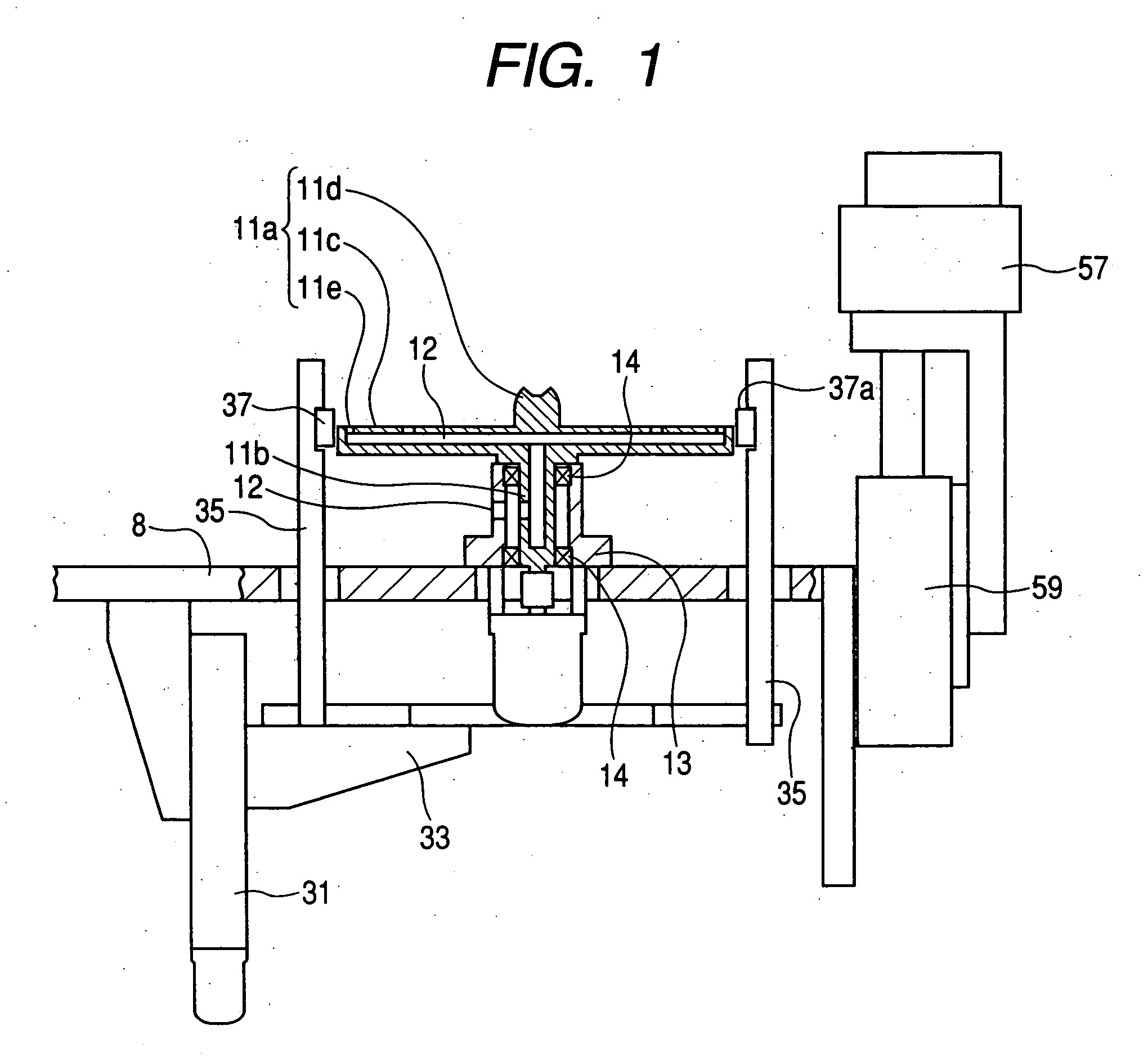
[0024] An embodiment of the present invention will hereinafter be described with reference to the drawings. FIGS. 1 to 6 schematically shows the main construction of an optical disc manufacturing apparatus, specifically a stamper stripping-off apparatus, according to the present invention, and are side views partly including a cross section along a plane perpendicular to the surface of a substrate when the substrate has been placed on the apparatus. FIG. 1 shows a state in which a substrate with a stamper is not mounted, FIG. 2 shows a state in which the substrate with the stamper has been mounted in the apparatus, and FIGS. 3 to 6 show a series of states of the apparatus in which the stamper is stripped off from the substrate.

[0025] The apparatus 1 has a substrate holding system 10, a stamper thrusting-up system 30 and a stamper holding system 50 as main constructions. In the present embodiment, a spacer layer 4 is formed on the entire upper surface of the substrate 3 mounted in t...


PUM

PropertyMeasurementUnit
Distanceaaaaaaaaaa

Abstract

The present invention makes it possible to strip off a stamper stuck on a resin layer for groove formation during the manufacture of an optical disc from the resin layer without imparting damage or the like to the stamper. The present invention achieves this object by having the steps of bringing about a state in which the stamper protrudes from a substrate by a predetermined width, rotating the substrate with the back surface of the disc-shaped substrate attracted and held, elevating rollers capable of rolling relative to a contacting surface contacting with the protruding portion simultaneously with the rotation, and continuously applying a force working in a direction to separate the protruding portion from the substrate in the circumferential direction of the stamper.

Description

BACKGROUND OF THE INVENTION [0001] 1. Field of the Invention [0002] This invention relates to an apparatus for and a method of manufacturing an optical disc typified by a so-called DVD disc or a blue-ray disc. More particularly, it relates to an apparatus for and a method of manufacturing an optical disc more suitable when manufacturing an optical disc of a type having two recording layers on one surface thereof. [0003] 2. Related Background Art [0004] For example, a blue-ray disc which is an optical recording medium called an optical disc is comprised of a substrate comprising polycarbonate or the like having a groove and a pit formed on the surface thereof, a sputter layer comprising a reflecting layer, a recording layer, etc. for example, by a sputtering method formed on the upper surface of the groove or the like, a light transmitting layer covering the upper surface of the sputter layer, and a protective layer covering the surface of the substrate. Also, there has been proposed...

Claims


Application Information

Patent Timeline
IPC IPC(8): B29D11/00B29D17/00
CPCB29C33/444B29D17/005Y10S425/81
Inventor KANEKO, YUKIOYODOKAWA, YOSHIMIUMEGA, TAKESHIUSAMI, MAMORUKOMAKI, TSUYOSHI
Owner TDK CORPARATION
Why Eureka
Try Eureka