
Processor control device

Active Publication Date: 2006-09-21
SEIKO EPSON CORP
View PDF10 Cites 4 Cited by
  • Summary
  • Abstract
  • Description
  • Claims
  • Application Information

AI Technical Summary

Benefits of technology

[0006] An advantage of the invention is to provide a processor control device which can perform the polling processing of a plurality of modules as well as preventing the load on the processor from increasing.
[0007] According to an aspect of the invention, a processor control device includes a processor executing an instruction, a module coupled to the processor through a bus and processing independently from the processor, the module is provided in a plural number and a polling processing unit coupled to each module, the polling processing unit stopping an operation of the processor depending on an execution status of the module processing at a time of an access request from the processor.
[0008] According to the aspect of the invention, it is possible to stop the operation of the processor until the processing of the module finishes, and the processor does not have to judge whether the processing of the module finished yet or not when the processor tries to access the module. Thereby, even in the case where more than one module is coupled to the processor through the bus, the processor does not need to judge which branch to process at the time of the polling processing and does not need to carry out the process of the branch. Accordingly, the processing load imposed on the processor can be reduced and it is possible to save the power consumed by the processor.
[0009] In this case, the processor control device may further include a clock control circuit supplying a clock signal to the processor, wherein the polling processing unit outputs a polling signal to the clock control circuit if the module is executing the processing when the module receive the access request from the processor. The polling signal is for stopping the clock signal supplied to the processor.
[0010] In this way, the module can stop the operation of the processor even if the module is in operation when the processor tries to access the module. Consequently, the processing load imposed on the processor can be reduced and it is possible to save the power consumed by the processor.
[0011] In this case, the module may include a single wait status register that assigns a setting to stop the operation of the processor based on the execution status of the module and a multi wait status register that assigns a setting to stop the operation of the processor based on execution statuses of the plurality of the modules.

Problems solved by technology

However, according to the hitherto known power saving technique, when a plurality of the DMAs exists and a DMA transfer is conducted, the CPU has to perform a polling processing by software and has to wait for the termination of the DMA transfer.
The CPU has to repeat such operation until the DMA transfer is ended and this increases the CPU load.

Method used


Image

  • Processor control device
  • Processor control device
  • Processor control device

Examples


first embodiment

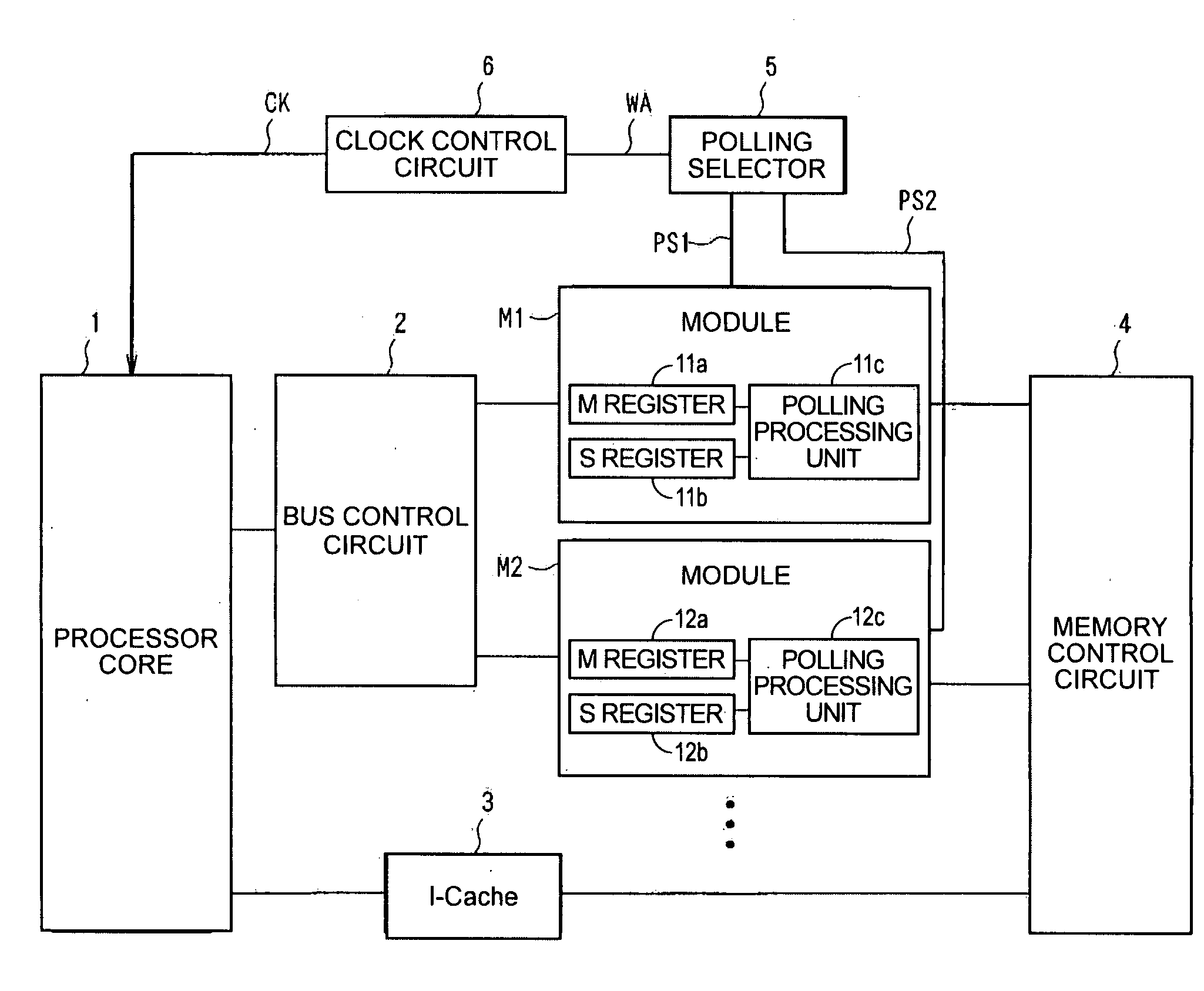
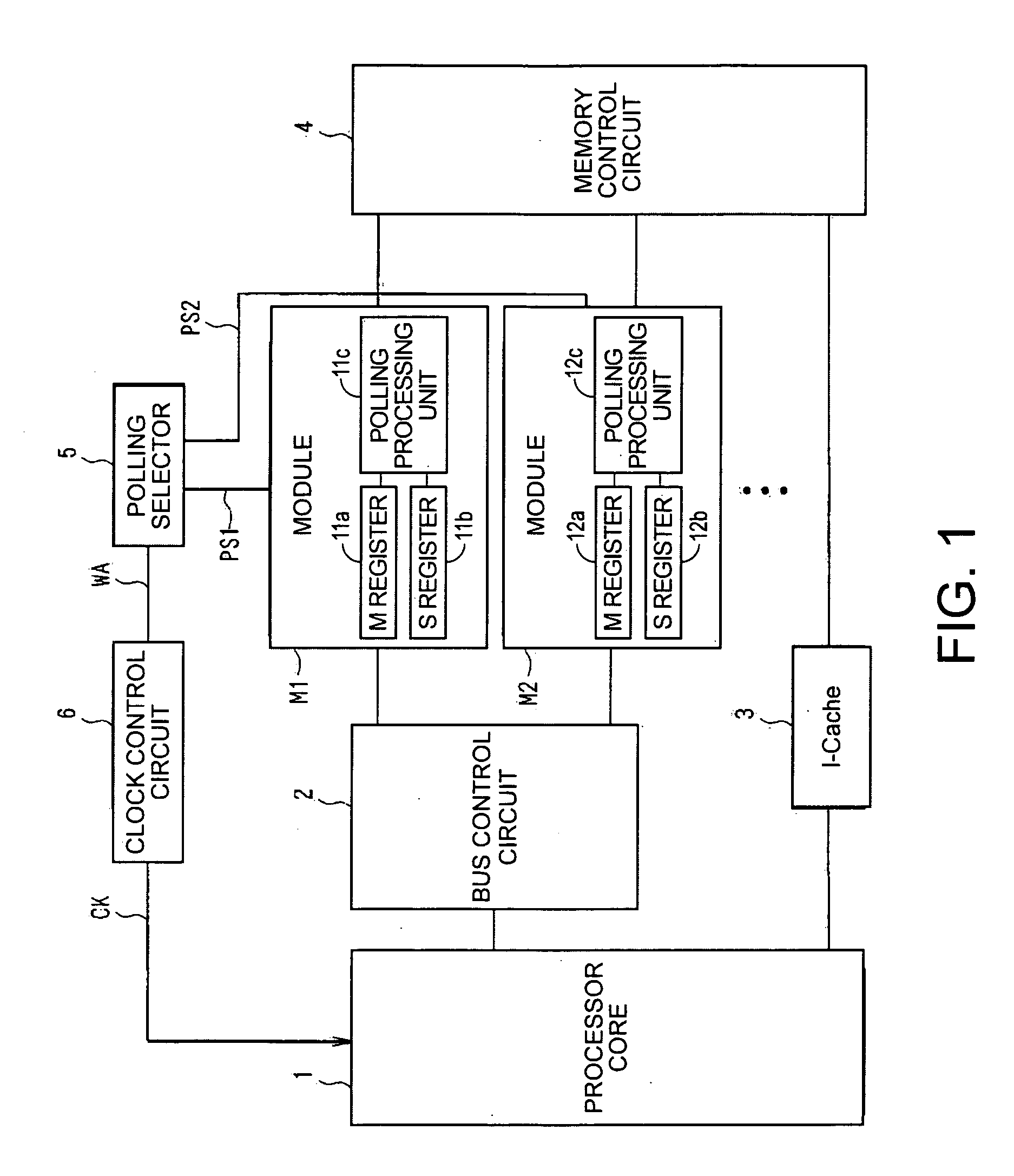
[0040]FIG. 1 is a block diagram showing a structure of a processor control device according to the invention.

[0041] As shown in FIG. 1, a processor core 1 is coupled to an instruction cache 3. The instruction cache 3 can obtain instructions that should be executed by the processor core 1 by accessing a memory through a memory control circuit 4. The instruction cache 3 then outputs the instructions to the processor core 1. The processor core 1 can execute a program in which the instructions are written by carrying out the instructions outputted from the instruction cache 3.

[0042] The processor core 1 is coupled to modules M1, M2 through a bus control circuit 2. The modules M1, M2 are also coupled to the memory control circuit 4. Peripheral circuits that can execute processing independently from the processor core 1 such as a direct memory access (DMA) controller and an I / O controller can be used as the modules M1, M2.

[0043] In the modules M1, M2, multi wait status registers 11a, 12...

second embodiment

[0102]FIG. 10 is a block diagram showing a structure of a processor control device according to the invention.

[0103] As shown in FIG. 10, a processor core 31 is coupled to an instruction cache 33. The instruction cache 33 can obtain instructions that should be executed by the processor core 31 by accessing a memory through a memory control circuit 34. The instruction cache 33 then outputs the instructions to the processor core 31. The processor core 31 can execute a program in which the instructions are written by carrying out the instructions outputted from the instruction cache 33.

[0104] The processor core 31 is coupled to modules M11, M12 through a bus control circuit 32. The modules M11, M12 are also coupled to the memory control circuit 34. In the modules M11, M12, set wait status registers 41a, 42a and wait status registers 41b, 42b and polling processing units 41c, 42c are provided. The set wait status registers 41a, 42a in the modules M11, M12 can assign settings that conti...


PUM


Abstract

A processor control device includes a processor executing an instruction, a module coupled to the processor through a bus and processing independently from the processor, the module is provided in a plural number and a polling processing unit coupled to each module, the polling processing unit stopping an operation of the processor depending on an execution status of the module processing at a time of an access request from the processor.

Description

BACKGROUND OF THE INVENTION [0001] 1. Technical Field [0002] The present invention relates to a processor control device, more particularly, a processor control device in which hardware performs a polling processing. [0003] 2. Related Art [0004] JP-A-8-83133 is an example of related art. The example discloses a technique for reducing power consumption of a central processing unit (CPU) by halting a clock signal provided to the CPU while a direct memory access (DMA) controller performs a DMA processing mode, in other words, while an I / O unit and a memory performs the DMA processing. [0005] However, according to the hitherto known power saving technique, when a plurality of the DMAs exists and a DMA transfer is conducted, the CPU has to perform a polling processing by software and has to wait for the termination of the DMA transfer. Therefore, when the plurality of the DMAs exists and a plurality of the DMA transfers is simultaneously performed, the CPU needs to read a value in a stat...

Claims


Application Information

Patent Timeline
IPC IPC(8): G06F13/00
CPCY02B60/1228G06F13/285Y02D10/00
Inventor HOSHINA, SHOJIISOMURA, MASAKAZUTODOROKI, AKINARI
Owner SEIKO EPSON CORP
Learn More