
Methods and systems providing adaptive feeder links for ground based beam forming and related systems and satellites

a feeder link and beam forming technology, applied in the field of satellite communications systems and methods, can solve the problems of increasing the cost, size and/or weight of the radioterminal, and the inability of the cellular satellite radioterminal system to reliably serve densely populated areas,

Inactive Publication Date: 2006-09-21
ATC TECH LLC
View PDF99 Cites 110 Cited by
  • Summary
  • Abstract
  • Description
  • Claims
  • Application Information

AI Technical Summary

Benefits of technology

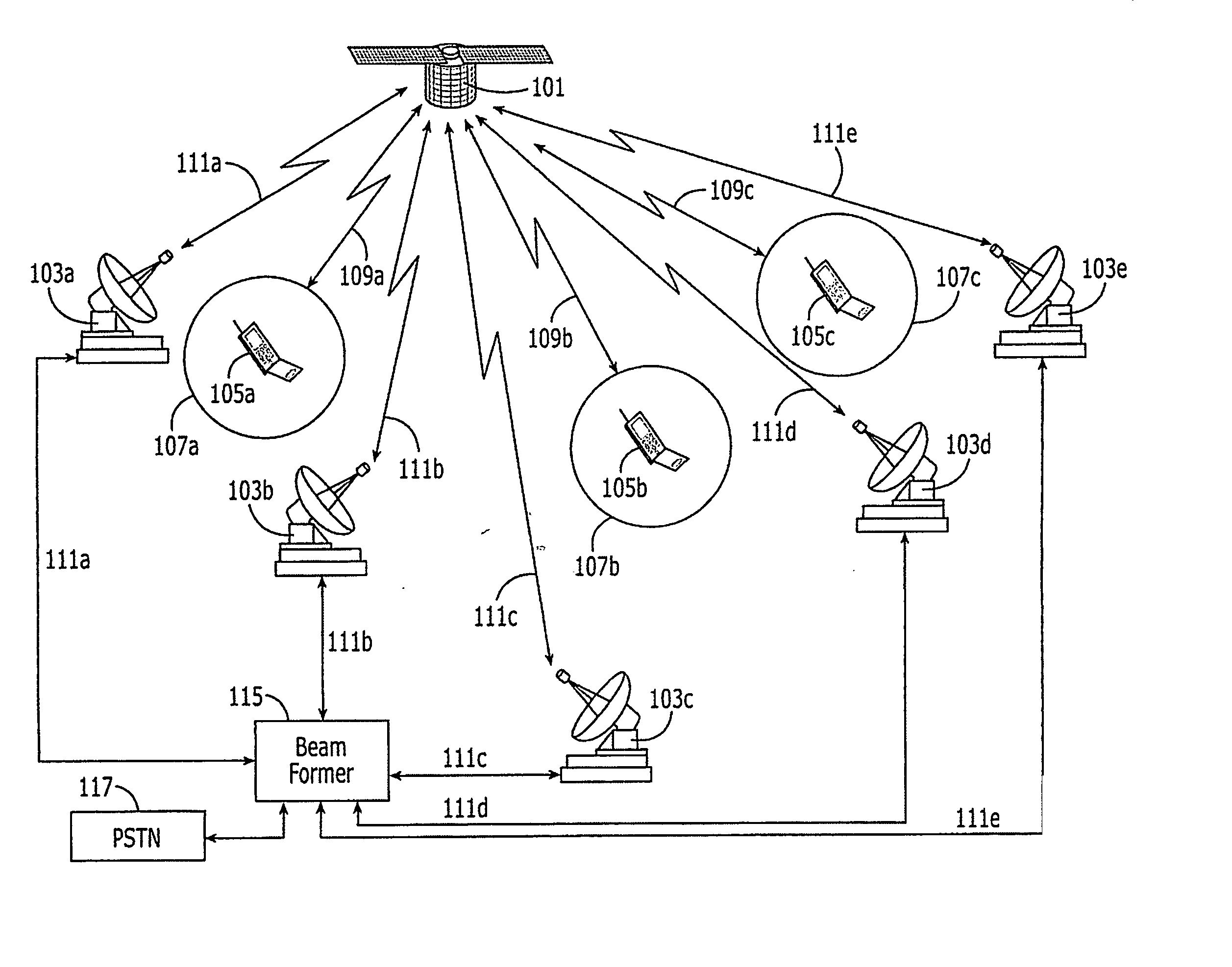
[0017] According to more embodiments of the present invention, a space-based communications system may include first and second gateways. The first gateway may be configured to provide a first feeder link between the first gateway and a satellite including a plurality of satellite service link antenna feed elements, and to communicate signals for first and second feed elements of the plurality of satellite service link antenna feed elements between the first gateway and the satellite over the first feeder link during a first time period. The first gateway may be further configured to communicate signals for the first feed element between the first gateway and the satellite over the first feeder link during a second time period. The second gateway may be configured to provide a second feeder link between the second gateway and the satellite, and to communicate signals for the second feed element between the second gateway and the satellite over the second feeder link during the second time period. Moreover, at least some feed elements of the plurality of satellite service link antenna feed elements may be configured to receive information from radioterminals over at least two different polarization orientations.
[0018] According to yet more embodiments of the present invention, a space-based communications system may include a gateway. The gateway may be configured to provide a feeder link with a satellite and to communicate signals for first and second feed elements of a plurality of satellite service link antenna feed elements at the satellite over the feeder link during a first time period. The signals of the first and second feed elements may be separated by a first frequency offset in a feeder link frequency band during the first time period. The gateway may be further configured to communicate signals for the first and second feed elements over the feeder link during a second time period, and the signals of the first and second feed elements may be separated by a second frequency offset in the feeder link frequency band during the second time period. In addition, the first and second frequency offsets may be different. Moreover, at least some feed elements of the plurality of satellite service link antenna feed elements may be configured to receive information from radioterminals over at least two different polarization orientations.

Problems solved by technology

In particular, it is known that it may be difficult for a cellular satellite radioterminal system to reliably serve densely populated areas, because a satellite signal may be blocked by high-rise structures and / or may not penetrate into buildings.
As a result, a satellite spectrum may be underutilized or unutilized in such areas.
Conventional dual band / dual mode radioterminal alternatives, such as the well known Thuraya, Iridium and / or Globalstar dual mode satellite / terrestrial radioterminals, duplicate some components (as a result of the different frequency bands and / or air interface protocols that are used between satellite and terrestrial communications), which can lead to increased cost, size and / or weight of the radioterminal.

Method used


Image

  • Methods and systems providing adaptive feeder links for ground based beam forming and related systems and satellites
  • Methods and systems providing adaptive feeder links for ground based beam forming and related systems and satellites
  • Methods and systems providing adaptive feeder links for ground based beam forming and related systems and satellites

Examples


Embodiment Construction

[0062] The present invention now will be described more fully hereinafter with reference to the accompanying drawings, in which embodiments of the invention are shown. This invention may, however, be embodied in many different forms and should not be construed as limited to the embodiments set forth herein. Rather, these embodiments are provided so that this disclosure will be thorough and complete, and will fully convey the scope of the invention to those skilled in the art. Like numbers refer to like elements throughout.

[0063] It will be understood that although the terms first, second, third and fourth etc., may be used herein to describe various elements, these elements should not be limited by these terms. These terms are only used to distinguish one element from another element. Thus, for example, a first element below could be termed a second, third or fourth element, and similarly, a second element may be termed a first, third or fourth element etc., without departing from ...


PUM


Abstract

A method of operating a communications system including a satellite may include providing communications feeder links between the satellite and a plurality of satellite gateways, and providing a communications service link between the satellite and at least one radioterminal using a plurality of satellite service link antenna feed elements. During a first time period, signals of first and second service link antenna feed elements of the plurality of service link antenna feed elements may be coupled between a first one of the plurality of satellite gateways and the first and second service link antenna feed elements. During a second time period, a signal of the first service link antenna feed element may be coupled between the first satellite gateway and the first service link antenna feed element, and a signal of the second service link antenna feed element may be coupled between a second one of the plurality of satellite gateways and the second service link antenna feed element. Related communications systems and satellites are also discussed.

Description

RELATED APPLICATIONS [0001] The present application claims the benefit of priority to U.S. Provisional Application No. 60 / 661,690 filed Mar. 15, 2005, the disclosure of which is hereby incorporated herein in its entirety by reference.FIELD OF THE INVENTION [0002] This invention relates to communications systems and methods, and more particularly to satellite communications systems and methods. BACKGROUND OF THE INVENTION [0003] Satellite communications systems and methods are widely used for wireless communications. Satellite communications systems and methods generally employ at least one space-based component, such as one or more satellites, that is / are configured to wirelessly communicate with a plurality of satellite radioterminals. [0004] A satellite radioterminal communications system or method may utilize a single satellite antenna pattern (beam or cell, also referred to as a global beam) covering an entire service region (service footprint) of the system. Alternatively, or i...

Claims


Application Information

Patent Timeline
Patent Type & Authority Applications(United States)
IPC IPC(8): H04B7/185H04Q7/20
CPCH04B7/2041
Inventor KARABINIS, PETER D.
Owner ATC TECH LLC
Learn More