
Method for high throughput drop dispensing of specific patterns

a technology of specific patterns and drop dispensing, which is applied in the direction of fluid controllers, laboratory glassware, instruments, etc., can solve the problems of inefficiency in precisely controlling such complex operations, the complexity of the task is further increased, and the difficulty of precisely, accurately and efficiently handling, transferring and delivering accurate microfluidic and sub-microfluidic quantities of liquids, etc., to achieve rapid and accurate dispensing, facilitate volume ejection, and high speed

Inactive Publication Date: 2006-09-21
BIODOT
View PDF12 Cites 45 Cited by
  • Summary
  • Abstract
  • Description
  • Claims
  • Application Information

AI Technical Summary

Benefits of technology

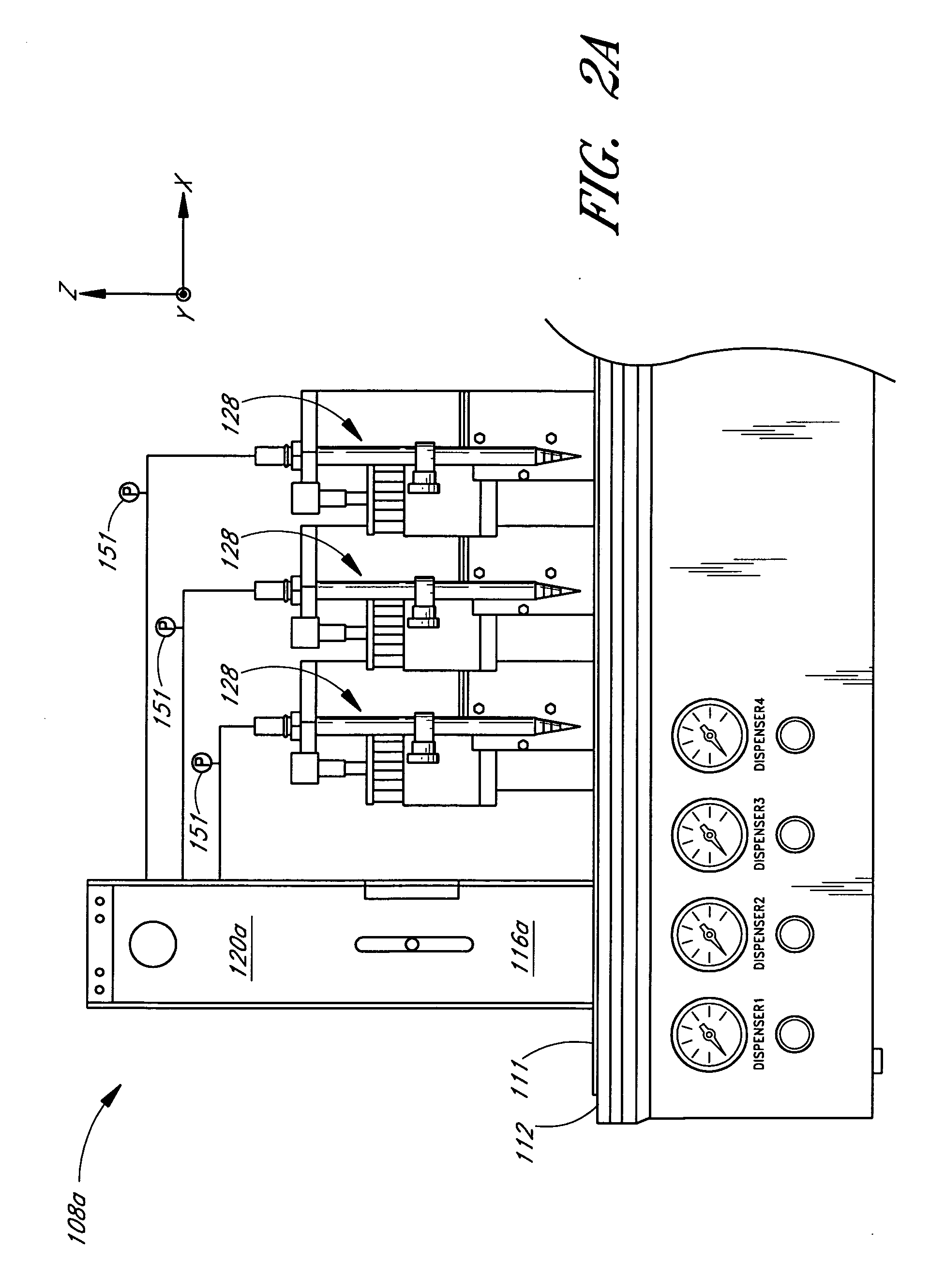
[0015] Certain embodiments relate to methods and systems for high-speed precision dispensing and / or aspirating of microfluidic and sub-microfluidic quantities of reagents and other liquids. In one embodiment, the operation of the systems is controlled by data accessed from a customized user-defined text file. Advantageously, the use of such text file control allows high-speed precision dispensing of one or more reagents with a wide dynamic range of dispense volumes in complex combinatorial patterns, ratios and arrays onto or into multiple predetermined locations of a desired target or substrate. This is particularly advantageous when a large number of permutations of different reagent and permutations of reagent volume ratios are involved. The systems may be operated in a high frequency modulated mode to further improve accuracy and reliability.
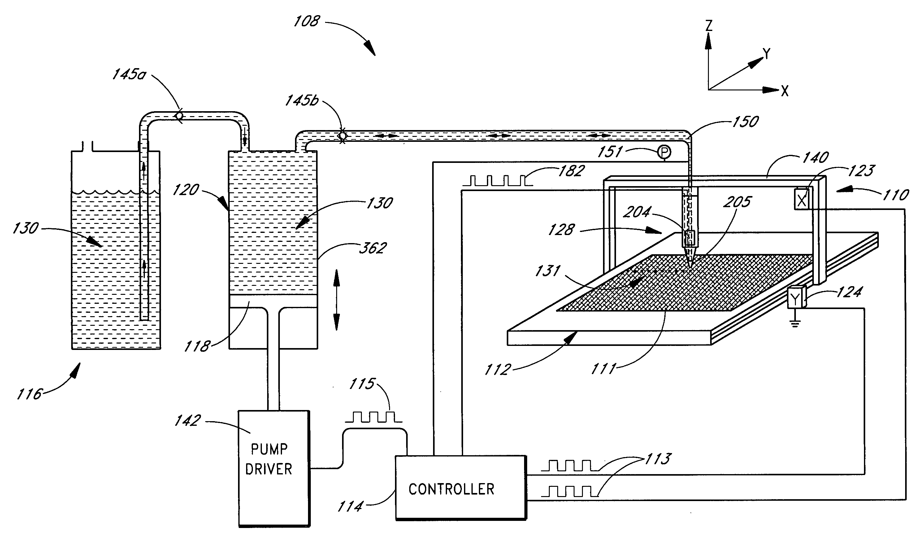
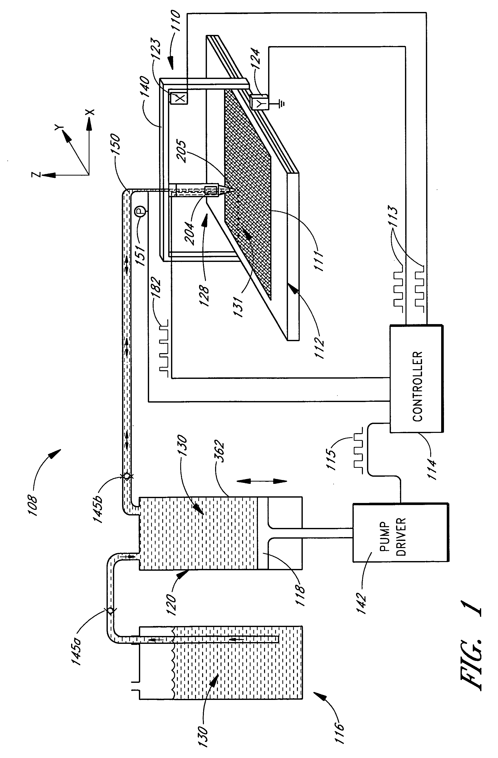
[0017] In accordance with one embodiment, a method is provided for high-speed precise dispensing of microfluidic quantities of a reagent onto or into a target. The method comprises the step of providing a dispenser adapted to form droplets of the reagent. A positive displacement pump is provided in fluid communication with the dispenser for metering precise quantities of the reagent to the dispenser. A controller is provided for controlling and coordinating the volume of the reagent dispensed at predetermined locations on or in the target. A user-defined text file is created. The text file contains lists of white space delimited numbers defining a dispense pattern that is to be formed on or in the target. The text file is accessible by the controller through a software program such that rapid and accurate dispensing is performed.
[0018] In accordance with another embodiment, a method is provided for high speed precise dispensing of a microfluidic quantity of a reagent onto or into a target. The method comprises the step of positively displacing a precise quantity of the reagent to a dispenser. A volume of the reagent is formed for ejection from the dispenser onto or into the target by opening and closing a solenoid valve at a frequency such that its operation is mechanically modulated so that it remains open in oscillation to facilitate ejection of the volume. The volume is an integral multiple of the precise quantity and less than or equal to the microfluidic quantity. The volume of the reagent dispensed at a predetermined location on or in the target is controlled and coordinated.

Problems solved by technology

It can be a difficult task to precisely, accurately and efficiently handle, transfer and deliver accurate microfluidic and sub-microfluidic quantities of liquids.
The complexity of the task is further increased when dealing with a wide variety of valuable reagents, a wide range of reagent dispense volumes and many permutations of reagents and reagent volume ratios.
Conventional technologies are generally inefficient in precisely controlling such complex operations.

Method used


Image

  • Method for high throughput drop dispensing of specific patterns
  • Method for high throughput drop dispensing of specific patterns
  • Method for high throughput drop dispensing of specific patterns

Examples


example 1

Programmed Line Mode

[0172]FIG. 10A is a schematic drawing illustrating a programmed line mode of dispense operation in accordance with one embodiment of the invention. In this mode, individual dots of the same or different amounts of fluid may be dispensed at different positions along a linear or non-linear path. The individual dots may or may not be colinear or evenly spaced, as desired. They may be spaced or offset from one another by a desired amount of spacing. This mode of operation may be useful, for example, for creating custom dot array patterns on a membrane or glass slide.

example 2

Synchronized Line Mode

[0173]FIG. 10B is a schematic drawing illustrating a synchronized mode of line dispense operation in accordance with one embodiment of the invention, such as for creating high-density dot arrays on a membrane or glass slide. This mode of dispense operation is particularly suited for dispensing reagent or other fluids into a conventional well plate array, such as illustrated in FIG. 10C, using either a single or multi-head dispenser. For example, a standard 96-well (8×12) well plate may be filled using a multi-head dispenser having a 1×8 dispense head array. The dispenser would dispense 8 parallel lines of 12 drops each with a spacing of 9 mm between drops and a line length of 99 mm. For a 1536-well (32×48) well plate array the same dispenser could be used to dispense 8 parallel lines of 48 drops each with a spacing of 2.25 mm between drops and a line length of 105.75 mm. The line pattern would be repeated 4 times to fill the well plate.

[0174] The same dispens...

example 3

Non-Synchronized Line Mode

[0175]FIG. 10D is a schematic drawing illustrating a non-synchronized mode of line dispense operation in accordance with one embodiment of the invention such as for creating continuous uniform lines on a flat substrate or for filling wells in a vision micro-well plate. A vision micro-well plate uses wells having an angular apex that separates each well. When dispensing a uniform continuous line of reagent the individual drops roll off the apex into the adjacent wells thus giving statistically accurate and even filling of wells.

[0176] In the non-synchronized mode of line dispense operation the valve dispense head and syringe pump operate at some harmonic of the motion stepper to produce a series of drops. For every N steps of the motion stepper one drop is dispensed. For example, if the motion stepper has a resolution of about 2 microns and the syringe pump has a resolution of 192,000 steps per full stroke then to dispense a 20.8 nL drop every 0.5 mm using...


PUM


Abstract

The invention relates to methods and systems for high throughput precision “on-the-fly” dispensing of sub-microfluidic quantities of reagents and other liquids in specific patterns onto or into a target substrate. In certain embodiments, a high speed process is provided for creating and / or repeating spaced lines or line segments by dispensing spaced arrays of drops on a target. One example of a target is a biosensor or the like with spaced electrodes, wherein each electrode receives a dispensed line.

Description

CROSS-REFERENCE TO RELATED APPLICATIONS [0001] This application is a continuation-in-part (CIP) of U.S. patent application Ser. No. 10 / 765,001, filed Jan. 26, 2004, which is a continuation of U.S. patent application Ser. No. 09 / 945,388, filed Aug. 30, 2001, now abandoned, which claims the benefit of U.S. Provisional Patent Application Ser. No. 60 / 229,003, filed Aug. 30, 2000, and which is a continuation-in part (CIP) of U.S. patent application Ser. No. 09 / 571,452, filed May 16, 2000, now abandoned, which is a divisional of U.S. patent application Ser. No. 09 / 146,614, filed Sep. 3, 1998, now U.S. Pat. No. 6,063,339, which claims the benefit of U.S. Provisional Application No. 60 / 070,988, filed Jan. 9, 1998, the entirety of each one of which is hereby incorporated by reference herein. [0002] This application is a continuation-in-part (CIP) of U.S. patent application Ser. No. 10 / 909,934, filed Aug. 2, 2004, now pending, which claims the benefit of U.S. Provisional Patent Application Se...

Claims


Application Information

Patent Timeline
IPC IPC(8): G01N1/10
CPCB01J19/0046Y10T436/2575B01J2219/00317B01J2219/00369B01J2219/00378B01J2219/00527B01J2219/00585B01J2219/0059B01J2219/00596B01J2219/00605B01J2219/00659B01J2219/00689B01J2219/00695B01J2219/00722B01L3/0265B01L3/5085B01L2200/0642B01L2200/14B01L2300/0829B01L2400/0487B01L2400/0666G01N35/1011G01N2035/1034B01J2219/00315
Inventor MILEDI, RICOCITEAU, HELENE A.S.TISONE, THOMAS C.
Owner BIODOT
Learn More