Disc drive carrier unit

a carrier unit and disc drive technology, applied in the field of carrier units, can solve the problems of assembly failure, assembly defect, assembly defect, etc., and achieve the effect of convenient assembly and disassembly

Inactive Publication Date: 2006-09-21
INVENTEC CORP
View PDF4 Cites 0 Cited by
  • Summary
  • Abstract
  • Description
  • Claims
  • Application Information

AI Technical Summary

Benefits of technology

[0010] In light of the drawback associated with prior art technology, one objective of the invention is to provide a disc drive carrier unit that is easily assembled and dismantled.
[0011] Another objective of the invention provides a disc drive carrier unit for reducing an assembly cost.
[0012] Another objective of the invention provides a disc drive carrier unit for reducing yield of the defective products.

Problems solved by technology

However, the computer casing 1 and the disc drive frames 11 and 13 of conventional technology are formed by the stamping technique with precision not easily controlled.
Consequently, this leads to misalignmnet with respective positioning holes on one lateral surface inside the computer casing 1 or on the bottom surface of another disc drive frame 11, making the assembly a defective product.
And perhaps, in the event when one of the four mounting holes 133 on the projecting pieces 131 is shifted in position, the disc drive frame is also regarded as a defective product due to adjustment failure.
Besides, it is not a convenient in such assembly since four screws are needed to secure a disc drive frame 13 on one lateral surface inside the computer casing 1 or on the bottom surface of another disc drive frame 11.
Moreover, the majority of a disc drive is surrounded by the disc drive frame 13, which is then secured on one lateral side inside the computer casing 1 or on the bottom surface of another disc drive frame 11, so that electromagnetic interference (EMI) is easily incurred during disc operation to harm a user's health condition, and electrostatic discharge (ESD) makes the disc drive vulnerable to additional damage from electrical overstress (EOS).
Therefore, these technology drawbacks are necessary to be improved for installing related computer devices, e.g., floppy disc drive, hard disc drive, CD-ROM drive, DVD-ROM drives, etc.

Method used


Image

  • Disc drive carrier unit
  • Disc drive carrier unit
  • Disc drive carrier unit

Examples


Embodiment Construction

[0027] To enable a further understanding of the structural features and the technical contents of the invention, the brief description of the drawings below is followed by the detailed description of embodiment.

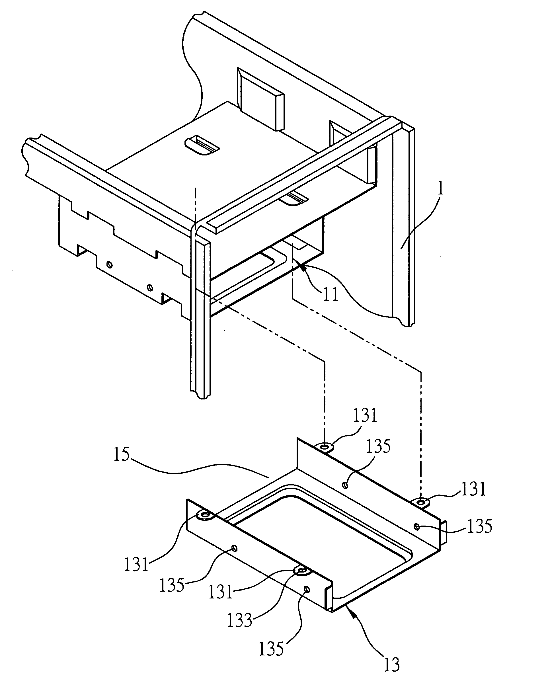
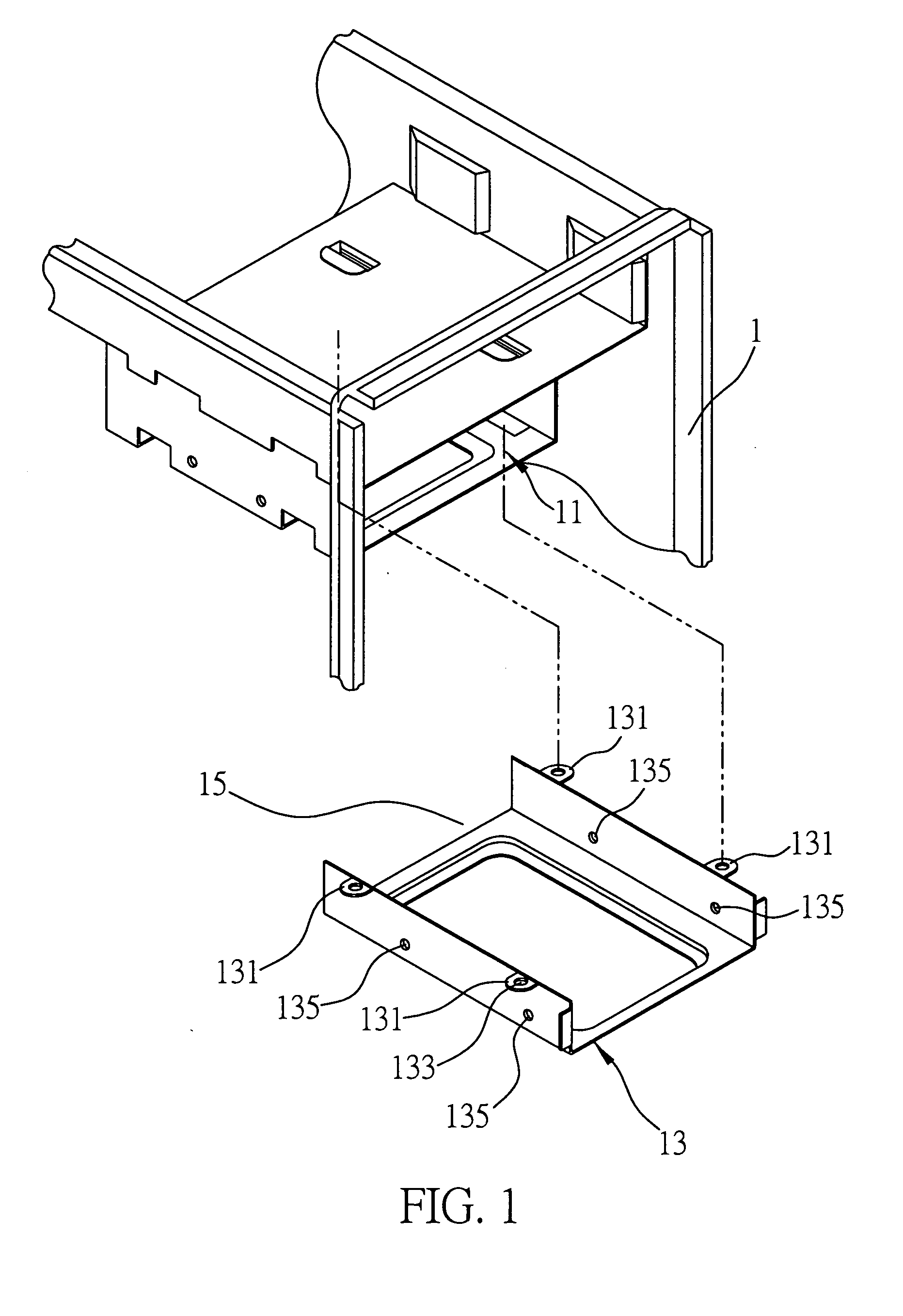
[0028]FIG. 2 is a schematic diagram illustrating a disc drive carrier unit according to the invention. As shown in FIG. 2, a disc drive carrier unit 2 comprises a frame 21, a second positioning piece 23 and two second fixation pieces 25. The frame 21, the second positioning piece 23 and the second fixation pieces 25 are made of conductive metal panels. The metal panels may be made of material selected from a group consisting of iron, copper, nickel, alloy of nickel and copper, alloy of nickel, copper and iron, or alloy of copper, nickel and gold. To manifest the features of the invention, conventional structures, such as computer casing, disc drive, and so on irrelevant to the invention are not further described herein.

[0029] The frame 21 is used to encompass and secure a d...


PUM


Abstract

A disc drive carrier unit installed on an installation surface of a computer casing is proposed. The installation surface has at least a first positioning piece and a first fixation piece, and both are perpendicular to each other. The disc drive carrier unit has a frame for encompassing and securing a disc drive, a second positioning piece for engaging with the first positioning piece, and at least a second fixation piece for correspondently securing to the first fixation piece. The second positioning piece of the disc drive carrier unit has an engaging function to replace the partial locking design of the conventional technology, for ease of assembly / disassembly and reduction of the assembly cost.

Description

BACKGROUND OF THE INVENTION [0001] 1) Field of the Invention [0002] This invention relates to an improved carrier unit, in particular, to a disc drive carrier unit for installing a disc drive within a computer casing. [0003] 2) Description of the Prior Art [0004] A wide use of electronic information device, particularly the computer has been epidemic to users of all ages. In this highly competitive age for specialization and professionalization, the related industries regarding computer hardware design, manufacturing and assembly have to constantly come up with research idea in the common goal of lowering manufacture cost to improve their competitiveness on the marketplace. Consequently, any improvement of computer hardware structure, which offers the potential for substantial structural simplification, ease of assembly or costs reduction, is regarded as an industrial innovation to computer hardware manufacturers, as well as in conformity with the spirit of the Patent Act. In view o...

Claims


Application Information

Patent Timeline
Patent Type & Authority Applications(United States)
IPC IPC(8): G06F1/16
CPCG06F1/184G06F1/187
Inventor YANG, YUNG-CHIHU, YUE-JUNCAI, MIKELE, LI-MING
Owner INVENTEC CORP
Why Eureka
Try Eureka