
Direct current power supply

a direct current and power supply technology, applied in secondary cells, emergency power supply arrangements, cell components, etc., can solve the problems of increasing the number of cell phone users, affecting the service life of the cell phone, etc., to achieve the effect of convenient and fast service life, low cost of operation and unique size and shap

Inactive Publication Date: 2006-09-21
ENERGIZER BRANDS
View PDF72 Cites 91 Cited by
  • Summary
  • Abstract
  • Description
  • Claims
  • Application Information

AI Technical Summary

Benefits of technology

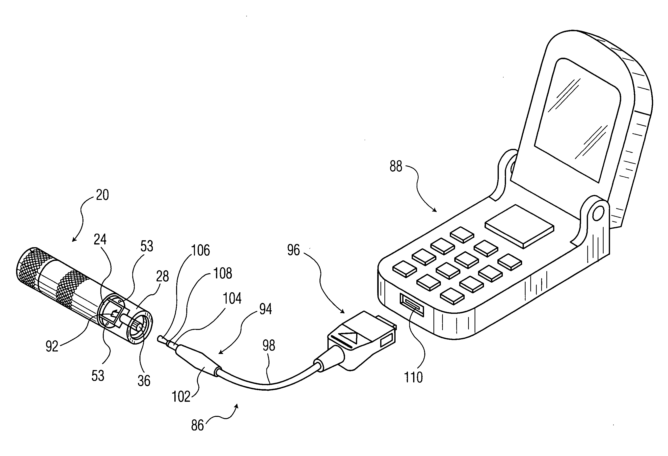
[0006] The present invention provides a portable direct current power supply that can be used to supply an electric current to a handheld electronic device, such as a cellular telephone, that utilizes a battery that has a unique size and shape. The present invention is small, light weight, and inexpensive to operate.
[0012] According to another aspect of the present invention, a method of assembling a battery powered power supply includes installing first and second human operable attaching members and a mechanically resilient, electrically conductive member in a first cover portion so that the conductive member urges the attaching members toward an interior surface of the first cover and provides a first battery contact. The method also includes snappingly attaching a second cover portion to a third cover portion to form a housing having first and second ends and a battery receiving region disposed therebetween, inserting a circuit board which carries an electrical connector, a second battery contact, and electrical circuitry which receives electrical energy from a battery and generates a power supply output for providing electrical energy to an external device in a fourth cover portion so that the electrical connector aligns with a first opening in the fourth cover portion. The method further includes snappingly attaching the fourth cover portion to the first end of the housing and using the attaching members to removably attach the first cover portion to the second end of the housing.
[0013] According to another aspect, a method of assembling a portable battery powered power supply includes placing a circuit board which carries an electrically conductive member, an electrical connector, a first battery contact, and electrical circuitry which receives electrical energy from a battery and generates a power supply output for providing electrical energy to an external device in a first cover portion so that the electrical connector aligns with a first opening in the first cover portion. The method also includes attaching the first cover portion to a second cover portion having first and second ends and a battery receiving region disposed therebetween so that the electrically conductive member makes an electrical contact with the first end of the first housing, and removably attaching a third cover portion which carries a second battery contact to the second end of the housing.

Problems solved by technology

Unfortunately, the inclusion of these features usually places additional demands on the rechargeable batteries that power the cell phones.
The net result is that the cell phones' run times become shorter and shorter due to the increased power demands.
The existence of these two trends (i.e. increased electrical demand and reduced battery size) has caused many cell phone users to experience a failed telephone call or data transmission due to the depletion of their phone's battery at an inopportune moment.
An additional trend that complicates resolving this problem is that most cell phones require a battery that has specific size and shape characteristics.
Furthermore, the recharging port built into the cell phones limit the type of charger that can be connected to the cell phone.
Collectively, these factors limit the consumer's ability to rapidly replace the depleted battery with another power supply.
Unfortunately, the battery pack and base unit tend to increase the size and weight of the cell phone, which is contrary to the consumer's desire, while also causing additional proliferation in the number of components the consumer needs to replace when the phone's battery is depleted.
Consequently, when the battery pack's battery is depleted the entire battery pack, including the plug, must be discarded which increases the consumer's cost.

Method used


Image

  • Direct current power supply
  • Direct current power supply
  • Direct current power supply

Examples


Embodiment Construction

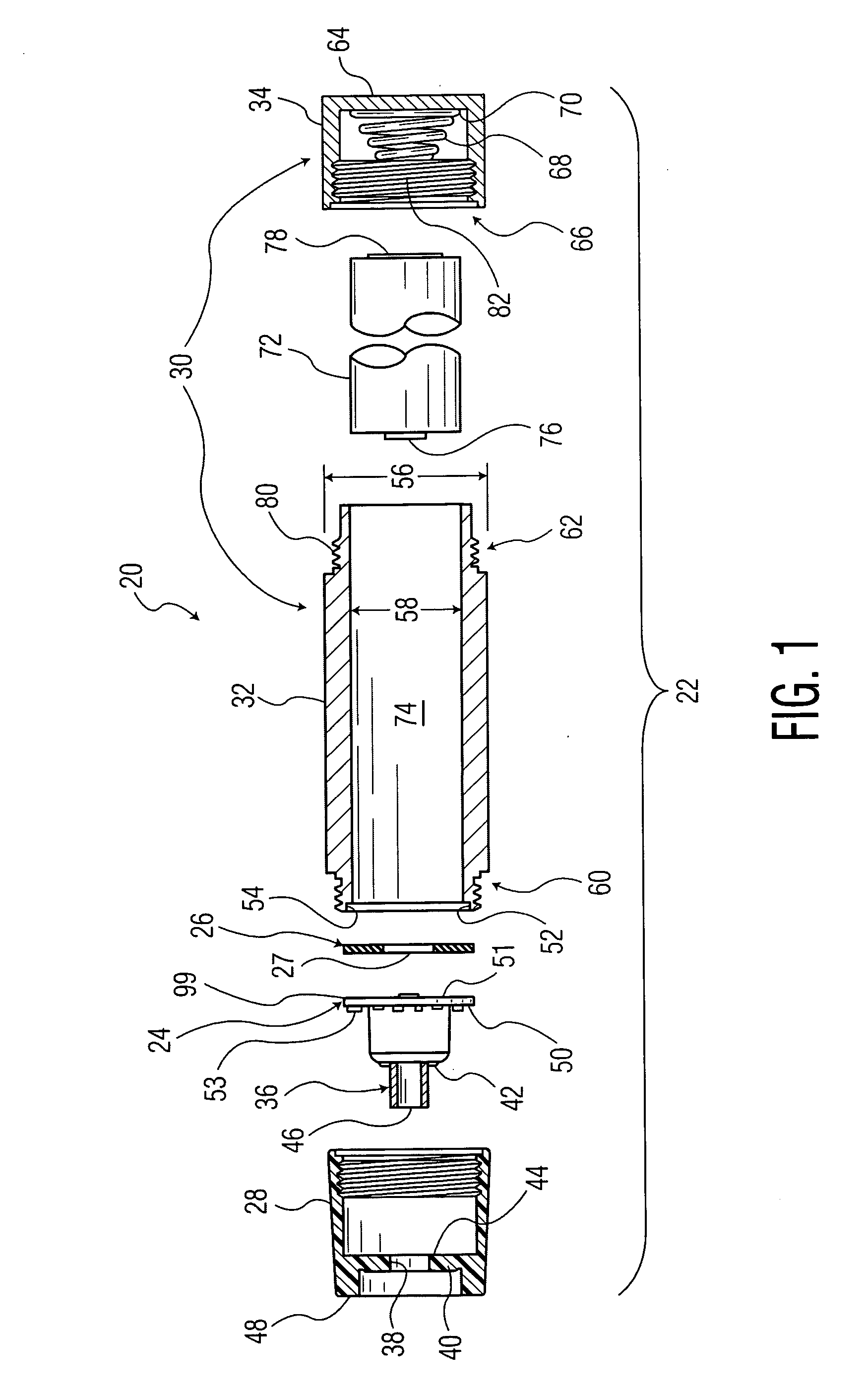
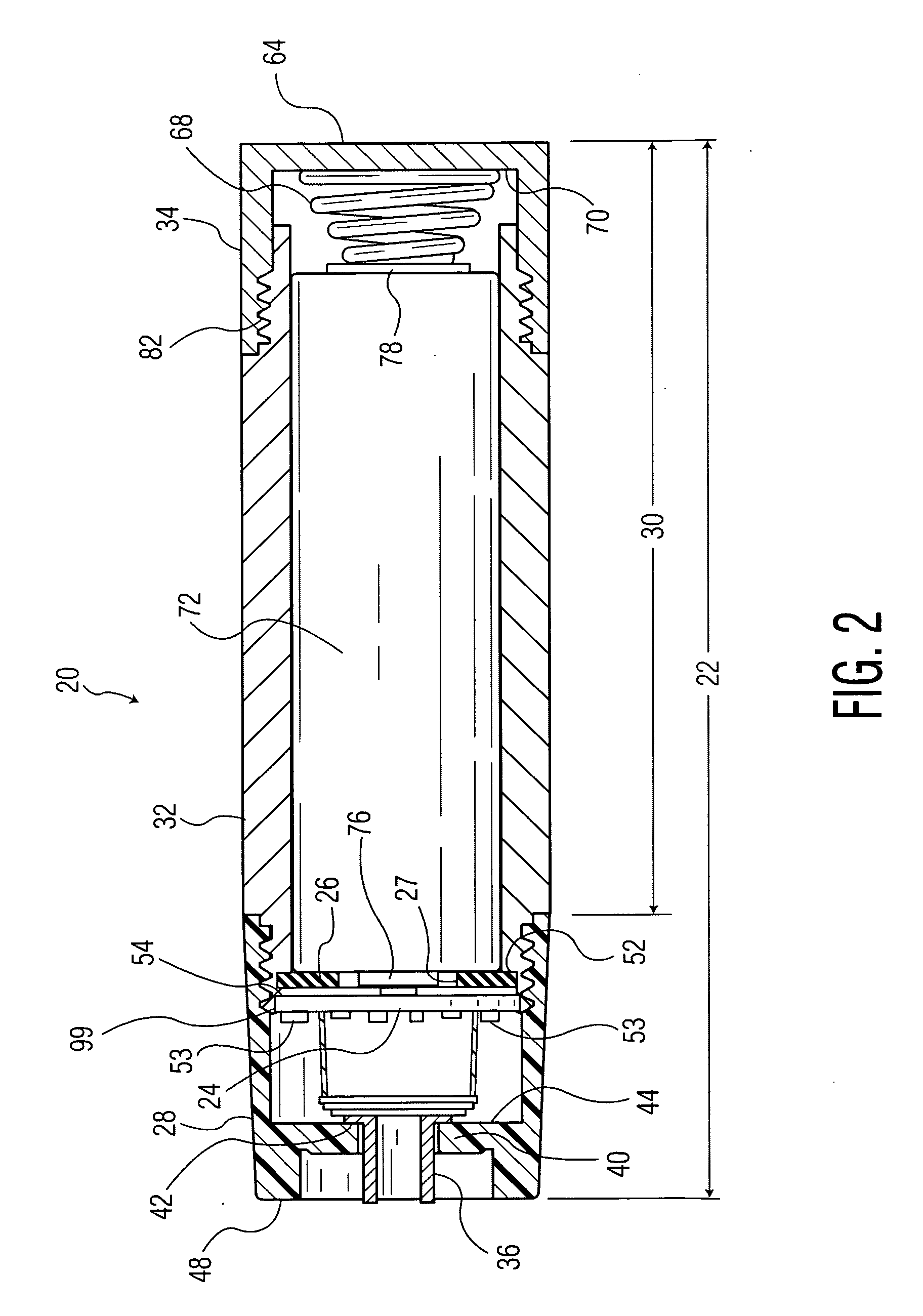
[0029] Referring now to the drawings and more particularly to FIG. 1, there is shown a cross-sectional view of a disassembled portable power supply 20 of this invention. The power supply generally comprises housing 22, circuit board 24, insulating ring 26, and electrochemical cell 72. Housing 22 includes an electrically nonconductive first section 28 and an electrically conductive second section 30 which can be further divided into first subsection 32 and second subsection 34. First section 28 is made of an electrically nonconductive and transparent material that will allow the consumer to view components on the circuit board. Second section 30 is made of aluminum which is an electrically conductive material. First section 28 and second section 30 can be secured to one another. Circuit board 24, commonly known as a printed circuit board (PCB), generally includes a thin electrically nonconductive disc shaped base member with a first planar surface 50 and a second planar surface 51. E...


PUM

PropertyMeasurementUnit
output voltageaaaaaaaaaa
open circuit voltageaaaaaaaaaa

Abstract

A portable electrochemical power supply for handheld electronic devices, such as cellular telephones, is disclosed. The power supply includes a housing with an electrical connector, a circuit board, and a removable electrochemical cell disposed therein. The circuit board carries power supply circuitry which receives electrical energy from the electrochemical cell and provides a power supply output for powering an external device.

Description

[0001] This application claims the benefit of U.S. Provisional Application No. 60 / 663,865, filed Mar. 21, 2005.BACKGROUND OF THE INVENTION [0002] This invention generally relates to a portable direct current power supply for a handheld electronic device. More particularly, this invention pertains to a direct current power supply for devices such as cellular phones. [0003] The proliferation of portable battery powered devices, such as cellular telephones, has increased dramatically in the last several years and this trend is expected to continue. The phones typically use a rechargeable battery that is built into the phone to provide the needed power. The length of time that the battery powers the phone is dependent primarily upon the size of the battery and the number of energy consuming features built into the phone. In response to consumer demand, cell phone manufacturers incorporate into the phones features such as the ability to send and receive digital pictures and / or text messa...

Claims


Application Information

Patent Timeline
Patent Type & Authority Applications(United States)
IPC IPC(8): H02J7/00H02J9/00H01M50/202H01M50/247H01M50/284H01M50/296
CPCH01M2/1022H01M10/425Y10T29/49895H02J7/0054H02J7/0044H02J7/342Y02E60/10H01M50/284H01M50/247H01M50/202H01M50/296
Inventor WEINSTEIN, NIRGABER, BENNY
Owner ENERGIZER BRANDS
Learn More