
Computer input apparatus

Active Publication Date: 2006-09-14
PIXART IMAGING INC
View PDF6 Cites 9 Cited by
  • Summary
  • Abstract
  • Description
  • Claims
  • Application Information

AI Technical Summary

Benefits of technology

[0016] One aspect of the present invention is to provide an optical mouse using a coherent light source and having an inexpensive safety mechanism.
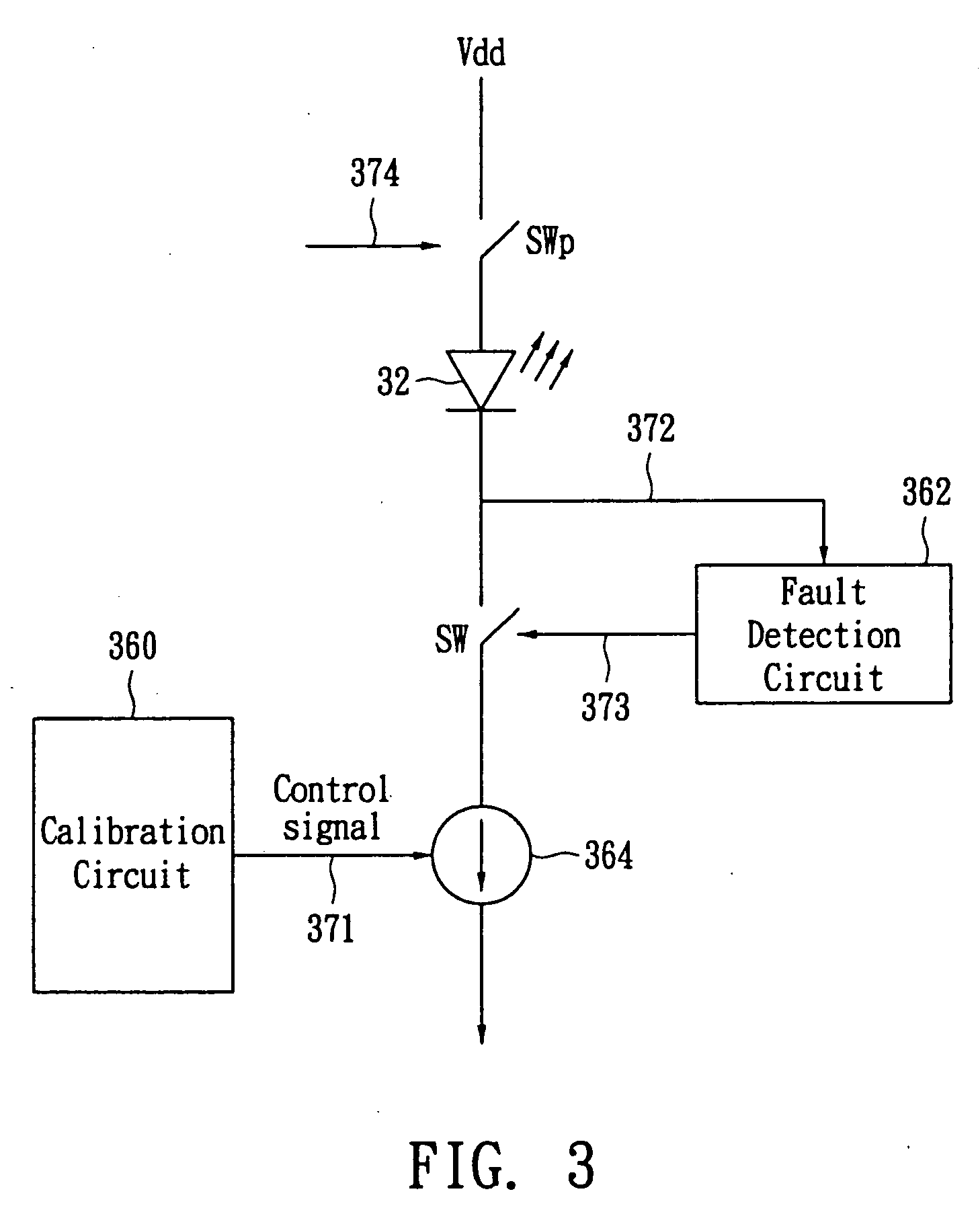
[0019] According to another aspect of the invention, a computer input apparatus comprises a housing; a light source; a sensor; and a control circuit; wherein the light source projects light on a working surface and the sensor captures reflected images from the working surface. The computer input apparatus does not require any lens to diminish optical power. The control circuit includes a calibration circuit for restricting the power of the emitting laser beams to be within a safety value, but above a minimum threshold value required for normal operations. Moreover, the control circuit preferably includes a fault detection circuit to monitor current flowing through the light source. If the current flowing through the light source exceed a safety limit, the fault detection circuit immediately cuts off the path of the current so as to avoid damage caused by the laser beams from the computer input apparatus.

Problems solved by technology

However, the performance of the mechanical mouse may degrade through extended use due to ball abrasion and dust.
Moreover, the mechanical mouse uses a bulky and heavy steel ball, which is also inconvenient for the user.
However, the above-mentioned optical mouse required a specialized mouse pad for normal operation, which limited the applicability thereof.
However, in above-mentioned prior art optical mice, complicated optical elements are required and the cost of the optical mouse is increased.
U.S. Patent publication 20040160998 of Gruhlke et al., entitled “Method and apparatus for modifying the spread of a laser beam,” mentions that optical mice containing laser devices are potentially hazardous to the eye.
However, this patent publication employs several complicated optical elements to dilute the light intensity of the laser beam or divert the direction of the optical paths.
For example, the patent utilized an optical train element including a focusing lens, a diffractive focusing vortex lens, a beam splitting device or a two dimensional diffraction grating whose cost is expensive.
This disclosure employs two resistors, at least two current legs and several comparators for detecting current passing through an LED; however, the two current legs may consume a lot of power from the LED and thus deteriorate the performance of the LED.
However, this disclosure requires a complex analog modulator or digital analog converter (DAC) to control the current flowing through the laser diode.

Method used


Image

  • Computer input apparatus
  • Computer input apparatus
  • Computer input apparatus

Examples


Embodiment Construction

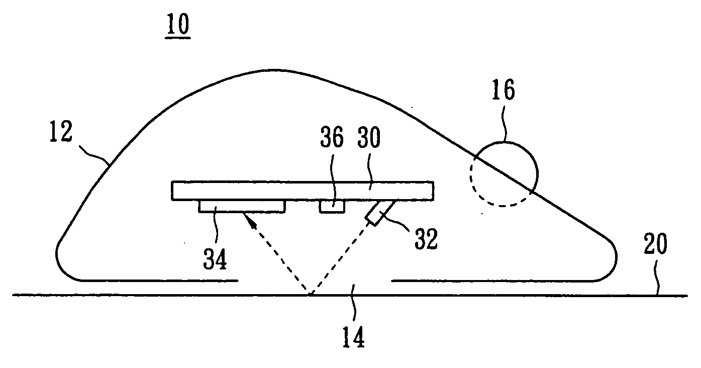
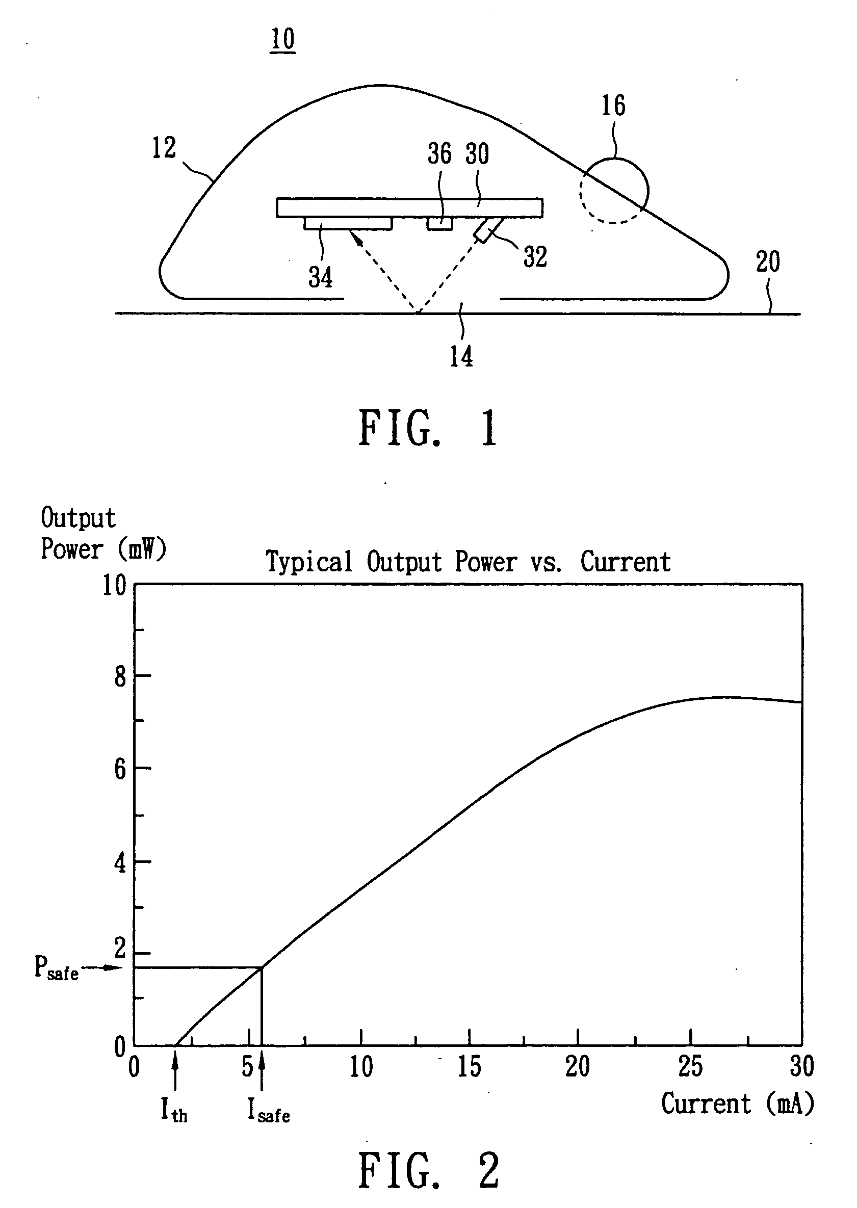
[0028]FIG. 1 shows a sectional view of an optical mouse 10 according to a preferred embodiment of the present invention. The optical mouse 10, which is placed on a working surface 20, comprises a housing 12, a circuit board 30 placed within the housing 12, a light source 32 arranged on the circuit board 30 and having a predetermined inclined angle with respect to the working surface 20, a sensor 34 arranged on the circuit board 30, and a control circuit 36 arranged on the circuit board 30. The predetermined inclined angle between the beam and the normal vector of the working surface 20 is, for example, about 47.5 degrees. However, other inclined angles can be used as long as the desired optical resolution is achieved. Moreover, the optical mouse 10 optionally comprises an aperture 14 at a bottom portion of the housing 12 and a third-axis wheel 16 arranged on a top face of the housing 12.

[0029] In another respect of the preferred embodiment, the optical mouse 10 placed on a working ...


PUM


Abstract

A computer input apparatus is disclosed which has improved safety control. The computer input apparatus includes a calibration circuit to control the operation current of a coherent light source to be above a minimum threshold required for normal operations, but below an upper threshold for safety reason. The computer input apparatus includes a fault detection circuit to monitor fault conditions. When this computer input apparatus employs a coherent light source, it does not require any optical lens to diminish optical power.

Description

CROSS REFERENCE [0001] This application is a continuation in part of co-pending application U.S. Ser. No. 11 / 353,308 filed on Feb. 14, 2006, which claims priority to U.S. Provisional Application No. 60 / 655,644 filed on Feb. 22, 2005.FIELD OF THE INVENTION [0002] The present invention generally relates to a computer input apparatus, and, in particular, to an optical mouse having a safeguard mechanism for eye safety. BACKGROUND OF THE INVENTION [0003] In personal computers, computer mice are popular means for inputting data and providing cursor control. A conventional mechanical mouse generally employs a rolling ball and at least two encoder wheels for x- and y-axis input operation. The respective encoder wheels are rotated by the rolling ball when a user moves the mouse along a flat surface, such as a mouse pad. The encoder wheels will intermittently block certain light propagation in the mouse and associated electronic signals are generated to control cursor movement on a computer d...

Claims


Application Information

Patent Timeline
IPC IPC(8): G09G5/08
CPCG06F3/0317G06F3/03543
Inventor LAI, SHENG-YEHKUO, MING-HUI
Owner PIXART IMAGING INC
Learn More