Tank system with fuel level gauge
a fuel level gauge and tank system technology, applied in liquid handling, instruments, packaged goods types, etc., can solve the problems of inability to reliably control the pressure refueling device, inability to reliably evaluate the management system, and severe malfunctions, and achieve high reliability and fault tolerance, negligible effect of fuel weight in the tank
- Summary
- Abstract
- Description
- Claims
- Application Information
AI Technical Summary
Benefits of technology
Problems solved by technology
Method used
Image
Examples
first embodiment
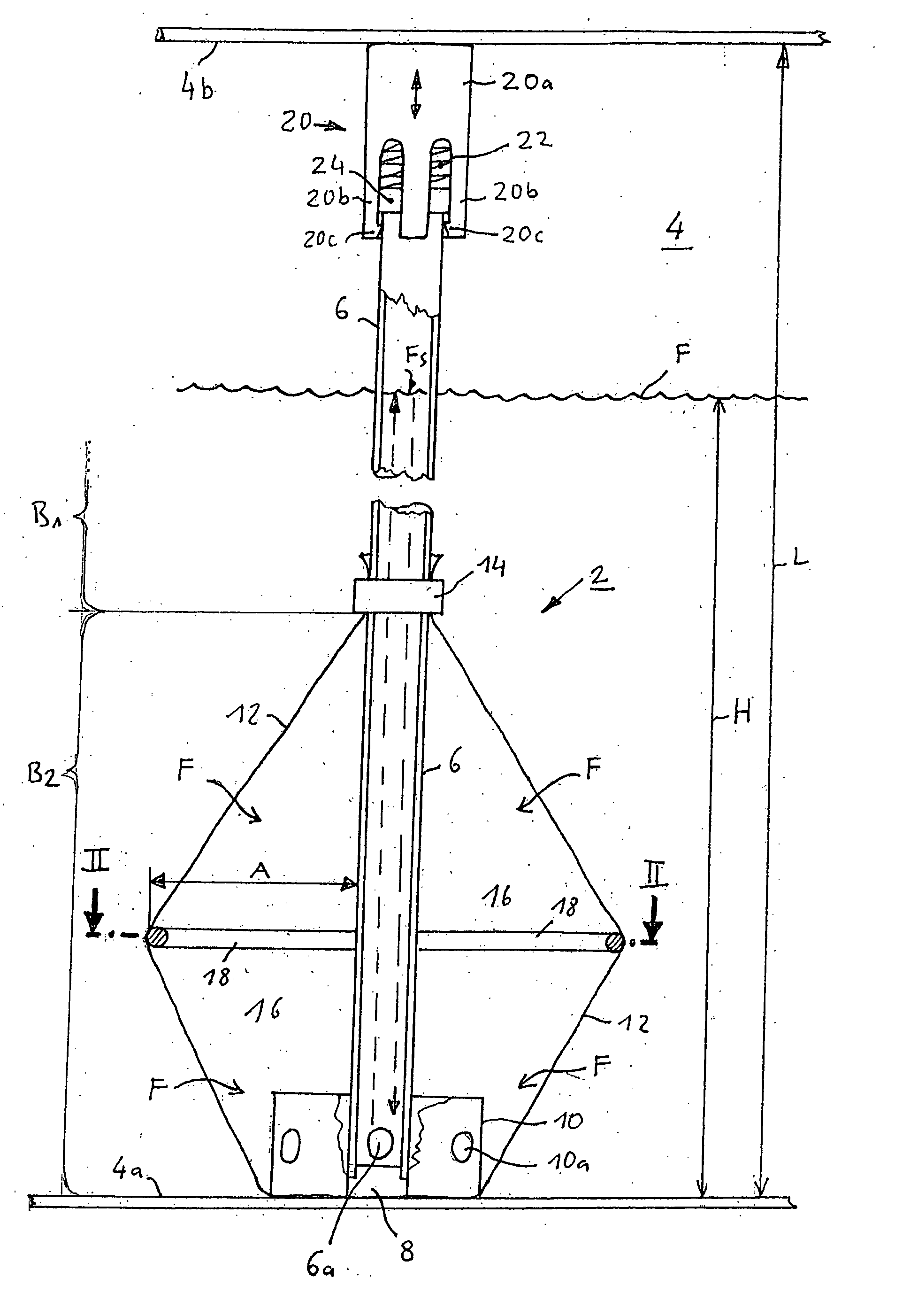
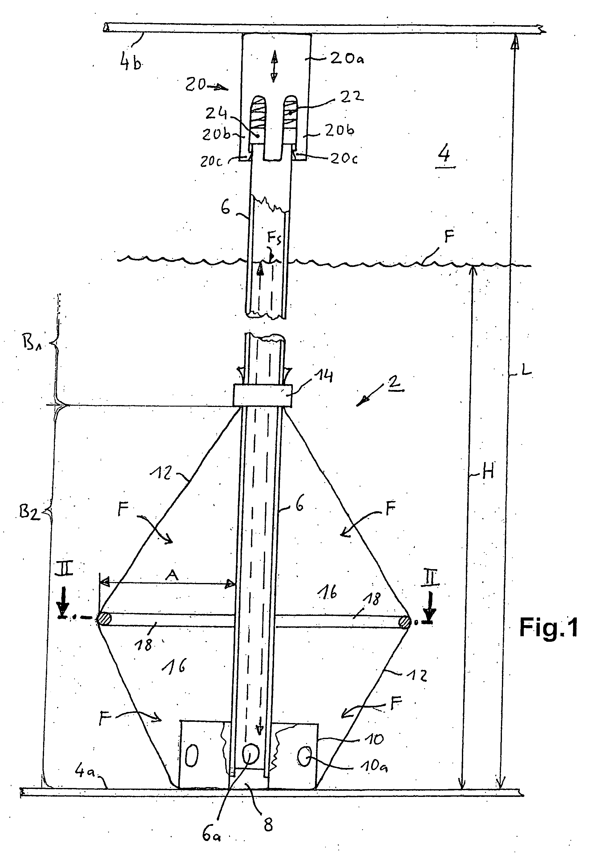
[0038]FIG. 1 shows a schematic, partially cutaway side view through a fuel level gauge 2 according to the invention mounted in a fuel tank 4 in a For the sake of clarity, only the bottom of the tank 4a and the top of the tank 4b of the fuel tank 4 are indicated The fuel level gauge 2 comprises a measuring pipe 6 configured as a riser pipe that has a fuel inlet opening 6a at one end area through which the fuel F can reach the inside of the measuring pipe 6. The measuring pipe 6 defines a measuring distance. A fuel level sensor 8 for measuring a fuel filling height H in the measuring pipe 6 is arranged at the lower end of the measuring pipe 6. This sensor 8 is preferably arranged in the vicinity of the fuel inlet opening 6a and has a measurement-sensitive sensor area. The sensor 8 in this example is an ultrasound fuel level sensor that, as the refueling operation progresses, measures the particular filling height H of the fuel F inside the measuring pipe 6 by measuring the propagatio...
second embodiment
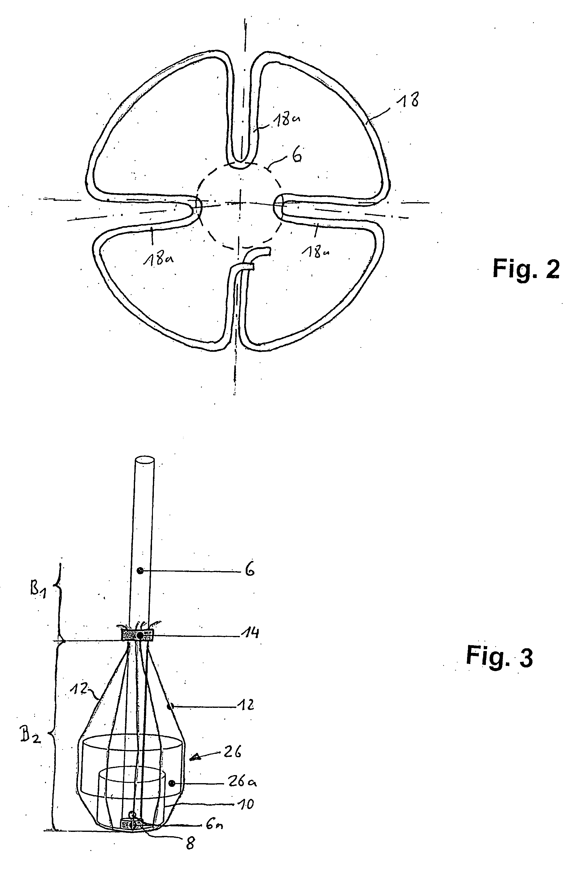
[0048]FIG. 3 shows a schematic three-dimensional, grid-like representation of a fuel level gauge 2 according to the invention in a This variant largely matches the one in FIGS. 1 and 2. Instead of the spacer 18 in the form of a bent wire ring, however, a different construction is used. As indicated in FIG. 3, a fuel density sensor 26 is provided in the second area B2 of the measuring pipe 6 and this fuel density sensor 26 has a virtually cylindrical sensor housing 26a that extends concentrically around the measuring pipe 6 and part of the labyrinth 10. In this example, the diameter of the sensor housing 26a is about 3 to 5 times the outer diameter of the measuring pipe 6. The sensor housing 26a serves as a spacer for the enveloping element 12 and thus fulfills an advantageous dual function. In FIG. 3, the enveloping element 12 is only indicated by a few lines in order to indicate the envelope shape of the enveloping element 12. The fuel density sensor 26 is a capacitive sensor that...
third embodiment
[0049]FIG. 4 shows a schematic longitudinal sectional view through a fuel level gauge 2 according to the invention in a third embodiment This variant uses various components that are already known from the embodiments of FIGS. 1 to 3, which is indicated by the use of the same reference numerals. However, the embodiment according to FIG. 4 differs from that of FIGS. 1 to 3 especially in terms of the arrangement and functionality of the fuel-permeable, thin-walled enveloping element 12.
[0050] As can be seen in FIG. 4, a housing 28 is installed on the measuring pipe 6, whereby said housing 28 surrounds the first area B1 of the measuring pipe 6 so as to seal it and encloses the second area B2 at a predefined distance A over a large surface, said second area B2 comprising at least the fuel inlet opening 6a and the measurement-sensitive area of the fuel level sensor 8. In this second area B2, the housing 28 forms a large-volume antechamber 16 between the inside of said housing 28 and the ...
PUM
 Abstract
Description
Claims
Application Information
 - R&D
- Intellectual Property
- Life Sciences
- Materials
- Tech Scout
- Unparalleled Data Quality
- Higher Quality Content
- 60% Fewer Hallucinations
Browse by: Latest US Patents, China's latest patents, Technical Efficacy Thesaurus, Application Domain, Technology Topic, Popular Technical Reports.
© 2025 PatSnap. All rights reserved.Legal|Privacy policy|Modern Slavery Act Transparency Statement|Sitemap|About US| Contact US: help@patsnap.com


