Method for producing ceramic structure

a technology of ceramic structure and ceramic plate, which is applied in the direction of fuels, lighting and heating apparatus, furnaces, etc., can solve the problems of increased production cost, increased production cost, and increased production cost, so as to reduce production cost, prevent explosion in furnaces, and achieve high production efficiency

Inactive Publication Date: 2006-09-07
NGK INSULATORS LTD
View PDF7 Cites 4 Cited by
  • Summary
  • Abstract
  • Description
  • Claims
  • Application Information

AI Technical Summary

Benefits of technology

[0013] A production method of a ceramic structure of the present invention can effectively prevent explosion in a furnace, reduce the production cost, and produce a ceramic structure with high production efficiency.

Problems solved by technology

That is, since a large amount of inflammable gas is generated due to decomposition of a large amount of organic type additive contained in a ceramic formed body, and a concentration of inflammable gas in the furnace is remarkably raised in degreasing / firing using a combustion furnace as described above, a danger of explosion in the furnace has arisen.
However, since this method uses an inert gas, it is necessary to substitute inert gas for gas in the furnace in addition to rise in production cost, and complex operations are forced in the process.
These problems still remain, and the method is still insufficient.
However, since the temperature rise speed is determined on the basis of a conventional rule based on experience in this method, there still arise problems that i) the method is yet insufficient from the viewpoint of effectively preventing explosion in a furnace, and that ii) temperature rise speed and an amount of the ceramic formed body is lowered to a level which is very low in comparison with a practically operable level to lower production efficiency, and thus there is left some room for improvement.
As described above, there has not been disclosed a method capable of reducing the production cost and producing a ceramic structure with high production efficiency in addition to effectively preventing explosion in a furnace.

Method used

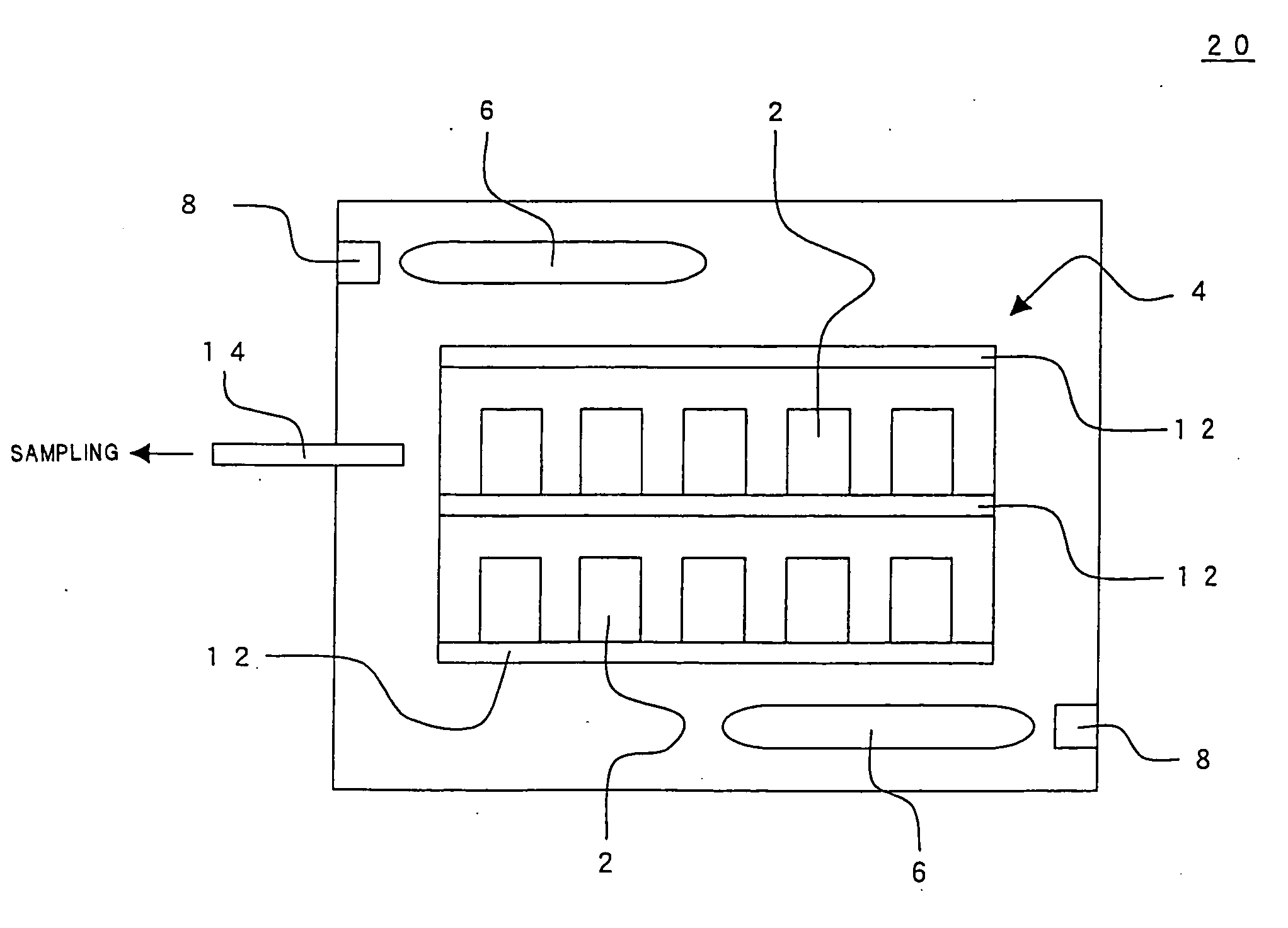
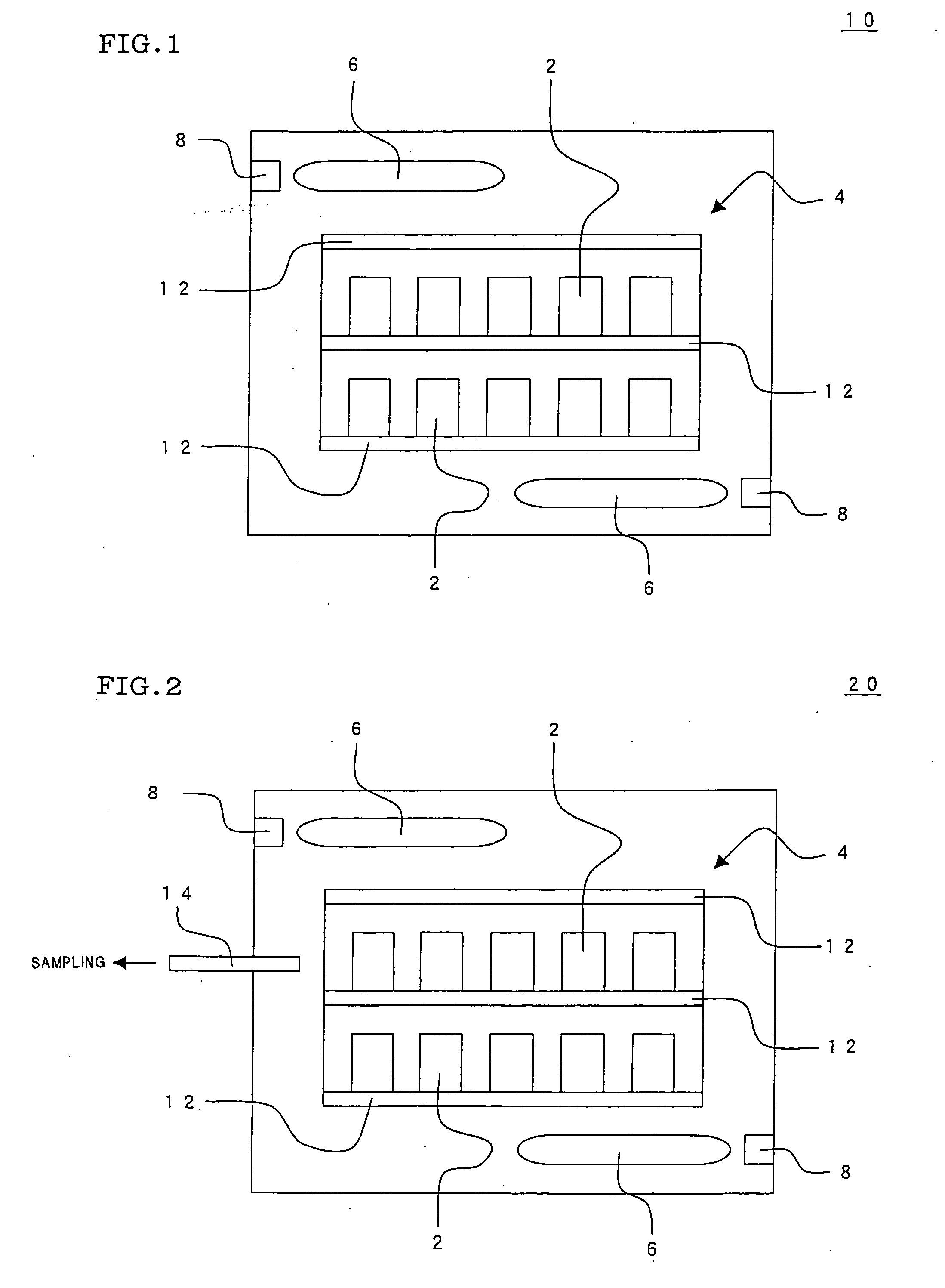

Image

  • Method for producing ceramic structure
  • Method for producing ceramic structure
  • Method for producing ceramic structure

Examples


example 1

[0049] Production of a ceramic structure was tried by degreasing and firing a ceramic formed body in a combustion furnace in an oxygen containing atmosphere.

[0050] There was used a ceramic formed body having a honeycomb structure having an outer diameter of 300 mm, a length of 300 mm, a cell shape of a square of about 1.8 mm×1.8 mm, a partition wall thickness of 0.3 mm, and a cell density of about 30 cells / cm2.

[0051] The above ceramic formed body was obtained by mixing 8 parts by weight of methyl cellulose as an organic binder, 20 parts by mass of a commercial poly(methyl methacrylate) resin as a pore forming agent, and 0.1 parts by mass of fatty acid soap (potassium laurate) as a dispersant with respect to 100 parts by mass of ceramic raw material containing kaolin, talc, aluminum hydroxide, alumina, and silica at the ratio of 18.5:40:15:14:12.5 to give a mixture, which was kneaded to obtain clay, which was subjected to extrusion forming and further dried by air.

[0052] As the co...

examples 2 to 4

[0060] In Examples 2 and 3, production of ceramic structures was tried in the same conditions as those in Comparative Example 1 except that amounts of air and fuel gas introduced was adjusted with maintaining temperature rise speed of 150 to 400° C. to control the total concentration of THC and carbon monoxide. In Example 4, production of a ceramic structure was tried in the same conditions as those in Comparative Example 1 except that temperature rise speed was adjusted according to amounts of air and fuel gas introduced to control the total concentration of THC and carbon monoxide. The results are shown in Table 1.

(Evaluation)

[0061] Though the conditions in Comparative Example 1 were completely the same as those in Example 1, the maximum amount of the total concentration of THC and carbon monoxide rose up to 2.00 vol. % due to a doubled amount of an organic type additive. This concentration exceeds 75% of 2.57 vol. %, which is the explosion lower limit concentration of the whol...


PUM

PropertyMeasurementUnit
temperatureaaaaaaaaaa

Abstract

There is provided a method for producing a ceramic structure, in which a concentration of at least one kind of inflammable gas (gas to be measured) in the combustion furnace is measured upon degreasing, and a condition such as temperature rise speed is adjusted according to a total concentration of the gas to be measured to control the total concentration of the gas to be measured to be a concentration of 0 to 75% of an explosion lower limit concentration of the whole gas to be measured. The method can effectively inhibit an explosion inside the furnace, can reduce the production cost, and can produce a ceramic structure with high production efficiency.

Description

BACKGROUND OF THE INVENTION AND RELATED ART STATEMENT [0001] The present invention relates to a method for producing a ceramic structure by degreasing and firing a ceramic formed body. [0002] Since ceramic material such as silica and alumina is excellent in mechanical strength and durability in comparison with organic material such as plastic, ceramic material is variously used as, for example, structure material and electric / electronic material. It is general that the ceramic material is used as a ceramic structure subjected to machining to have a shape suitable for each usage. For a use such as a diesel particulate filter (DPF) for trapping particulate matter (PM) exhausted from a diesel engine (diesel engine or the like of an automobile), there is suitably used a honeycomb-shaped ceramic structure (ceramic honeycomb structure) having a large number of cells formed and separated from each other by partition walls. [0003] As a method for producing such a ceramic structure, there ha...

Claims


Application Information

Patent Timeline
Patent Type & Authority Applications(United States)
IPC IPC(8): C10L1/12
CPCC04B35/638C04B35/64C04B2235/6583F27D19/00F27D21/00
Inventor NOGUCHI, YASUSHI
Owner NGK INSULATORS LTD
Why Eureka
Try Eureka