
Active crossover for use with multi-driver in-ear monitors

Active Publication Date: 2006-08-31
LOGITECH INT
View PDF2 Cites 17 Cited by
  • Summary
  • Abstract
  • Description
  • Claims
  • Application Information

AI Technical Summary

Benefits of technology

[0009] The present invention provides a headset with an active crossover network. The headset is coupled to an audio source using either a wired connection (e.g., stereo jack, USB connection, or other compatible interface) or a wireless connection (e.g., Bluetooth, 802.11b, 802.11g, etc.). The active crossover network, utilizing either analog or digital filtering, divides each channel of the incoming audio signal into multiple frequency regions sufficient for the number of drivers contained within each in-ear monitor of the headset. The output from the network's filters is amplified using either single channel or multi-channel amplifies. Preferabl

Problems solved by technology

Second, due to their size, in-ear monitors have little, if any, effect on the mobility of the user (e.g., musician, sports enthusiast, etc.).
Unfortunately due to the size of such drivers, earpieces utilizing diaphragm drivers are typically limited to a single diaphragm.
As diaphragm-based monitors have significant frequency roll off above 4 kHz, an earpiece with a single diaphragm cannot achieve the desired upper frequency response while still providing an accurate low frequency response.
Due to the inherent cost of armature drivers, however, they are typically only found in hearing aids and high-end in-ear monitors.
A single armature is capable of accurately reproducing low-frequency audio or high-frequency audio, but incapable of providing high-fidelity performance across all frequencies.

Method used


Image

  • Active crossover for use with multi-driver in-ear monitors
  • Active crossover for use with multi-driver in-ear monitors
  • Active crossover for use with multi-driver in-ear monitors

Examples


Embodiment Construction

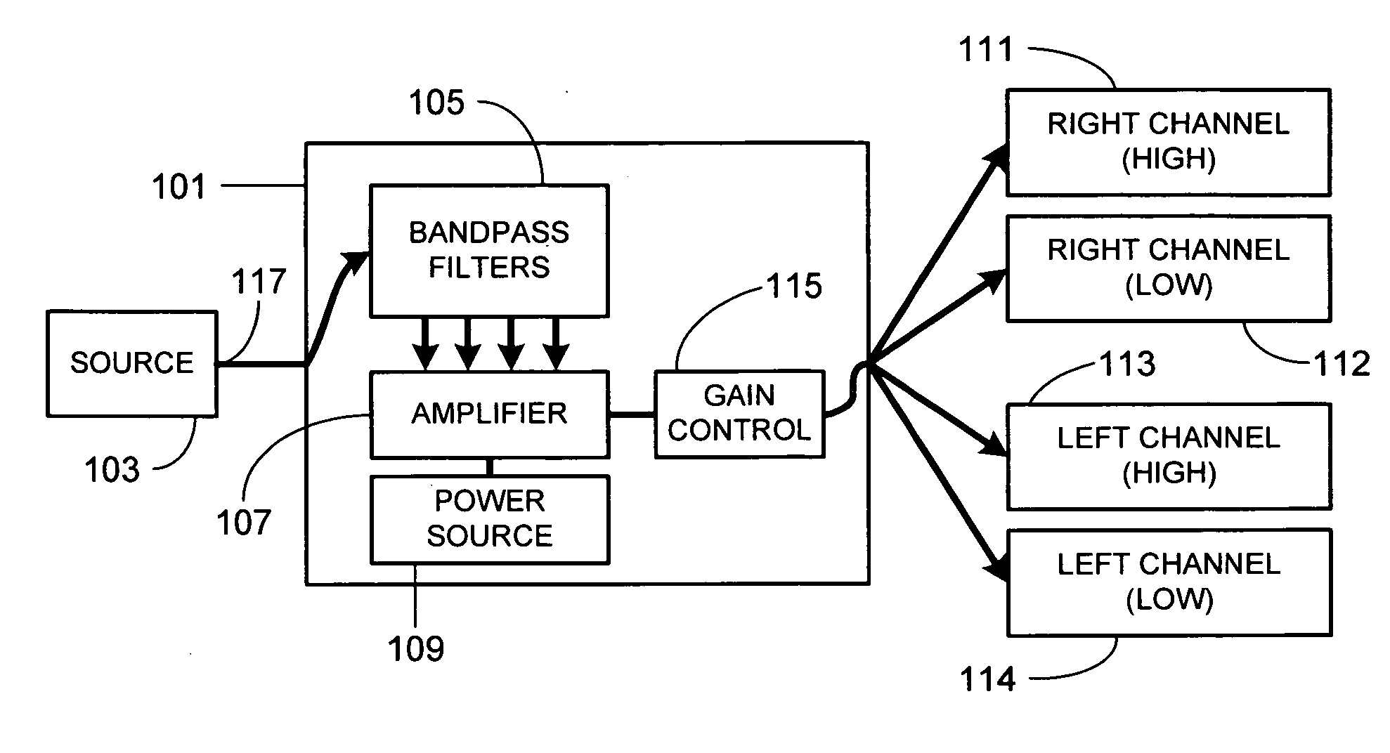
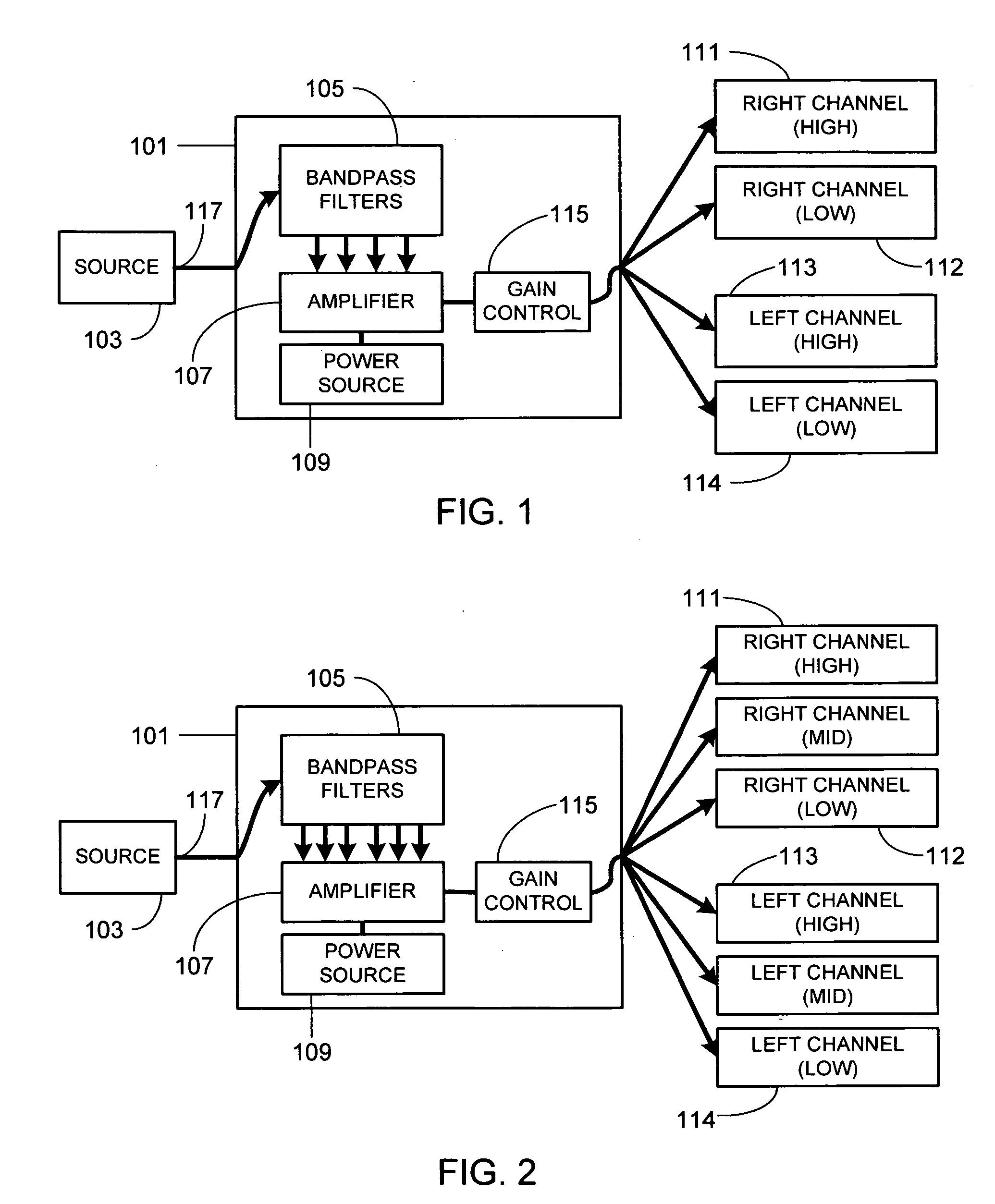
[0024]FIG. 1 is a block diagram illustrating the primary components of the invention. The active crossover network 101 accepts an audio input signal from a source 103. The filters 105 (e.g., bandpass filters) within the crossover network separate the audio spectrum of the incoming audio signal into the appropriate number of frequency regions based on the number of drivers per channel. Thus in the example illustrated in FIG. 1, bandpass filters 105 separate the incoming audio spectrum into left and right channel high frequencies and left and right channel low frequencies. After frequency separation, each frequency region is amplified using either a single multi-channel amplifier 107 as shown, or multiple single channel amplifiers. Amplifier 107 is coupled to a power source 109. Drivers 111-114 are coupled to amplifier 107, drivers 111-114 outputting, respectively, right channel, high frequencies; right channel, low frequencies; left channel, high frequencies; and left channel, low fr...


PUM


Abstract

A headset with an active crossover network is provided. The headset is coupled to an audio source using either a wired connection or a wireless connection. The active crossover network, utilizing either analog or digital filtering, divides each channel of the incoming audio signal from the audio source into multiple frequency regions sufficient for the number of drivers contained within each in-ear monitor of the headset. The output from the network's filters is amplified using either single channel or multi-channel amplifies. Preferably, gain control circuitry is used to control the gain of the amplifier(s) and thus the volume produced by the drivers. More preferably, the gain of the gain control circuitry is adjustable. The headset includes a power source that is coupled to the amplifier(s) and, if necessary, the network's filters. The power source can be included within some portion of the headset or included within the wireless interface. Alternately, an external power source can be used, for example one associated with the audio source.

Description

CROSS-REFERENCES TO RELATED APPLICATIONS [0001] This application is a continuation-in-part of U.S. patent application Ser. No. 11 / 034,144, filed Jan. 12, 2005 and claims the benefit of U.S. Provisional Patent Application Ser. No. 60 / 696,685, filed Jul. 5, 2005, the disclosures of which are incorporated herein by reference for any and all purposes.FIELD OF THE INVENTION [0002] The present invention relates generally to audio monitors and, more particularly, to multi-driver in-ear monitors. BACKGROUND OF THE INVENTION [0003] Earpieces, also referred to as in-ear monitors and canalphones, are commonly used to listen to both recorded and live music. A typical recorded music application would involve plugging the earpiece into a music player such as a CD player, flash or hard drive based MP3 player, home stereo or similar device using the earpiece's headphone jack. Alternately, the earpiece can be wirelessly coupled to the music player. In a typical live music application, an on-stage mu...

Claims


Application Information

Patent Timeline
IPC IPC(8): H04R1/10H04R5/00
CPCH04R3/14H04R2420/07H04R2499/11H04S1/005H04S1/007H04S7/30
Inventor HARVEY, JERRY J.DYER, MEDFORD ALAN
Owner LOGITECH INT
Learn More