Pressure point food container, storage, and mixing system
- Summary
- Abstract
- Description
- Claims
- Application Information
AI Technical Summary
Benefits of technology
Problems solved by technology
Method used
Image
Examples
first preferred embodiment
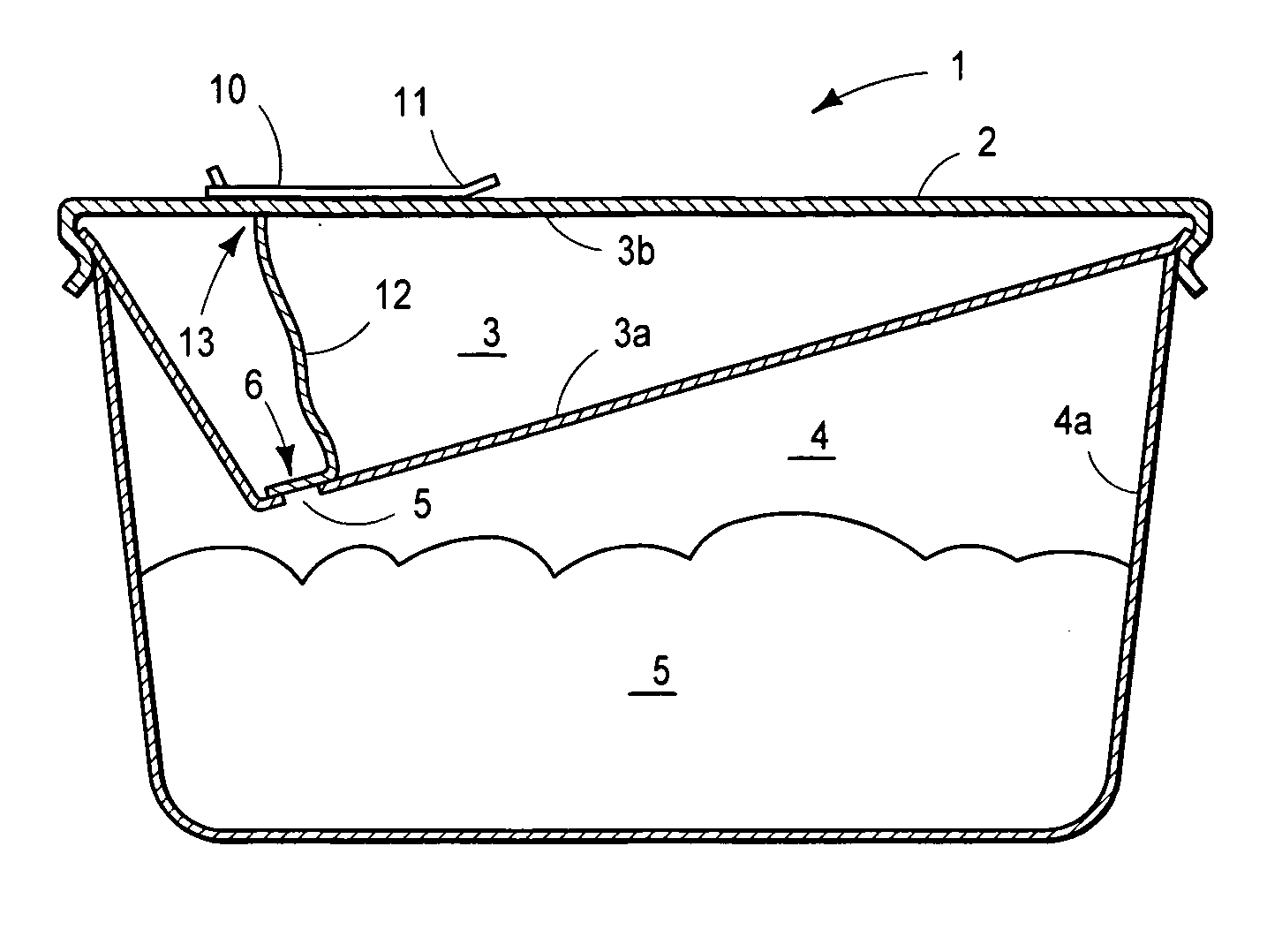
[0064] Referring initially to FIG. 1, a first embodiment of the present invention is shown in cross section. In FIG. 1 a container 1 for storing and transporting foods is shown with a closure 2 is situated across top of container 1. With closure 2 in place over top of container 1, separate first compartment 3 and second compartment 4 are created in container 1. Separate first compartment 3 may be created by compartment wall 3a and closure 2 or, in the alternative, separate first compartment 3 may be created by wall 3a and a second wall 3b (not shown) residing under closure 2. Separate second compartment 4 may be created by container wall 4a and backside of wall 3a of separate first compartment 3. Separate first compartment 3 and separate second compartment 4 are closed and sealed, generally after the interior of each compartment is sterilized, and each compartment is filled with a substance, generally separately contained foods in combination with inert gas, such as nitrogen, to ret...
second preferred embodiment
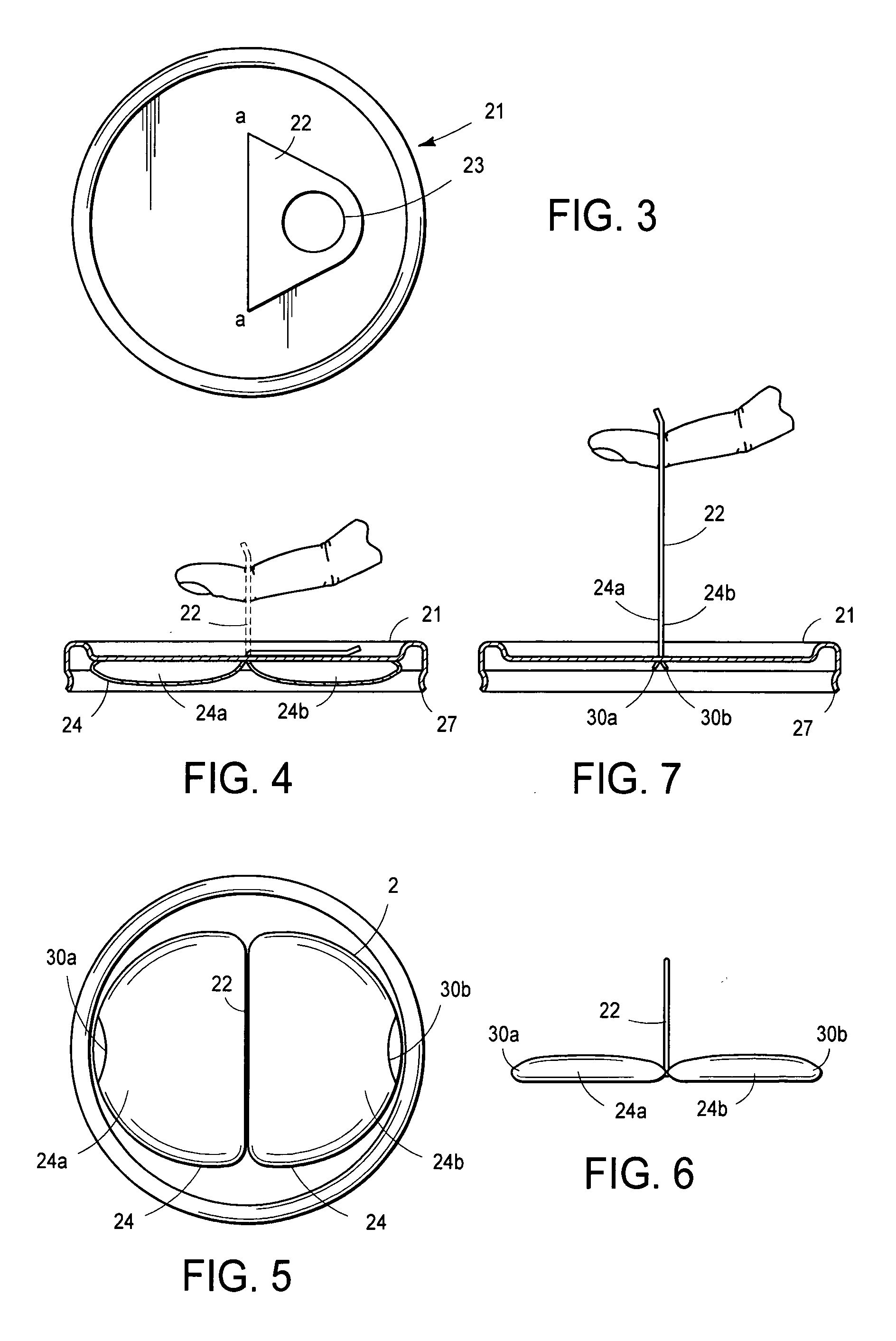
[0068] Referring now to FIG. 3, a second embodiment of the present invention is shown in a top down view drawing. In FIG. 3, lid 21 of the second embodiment also shows a pull tab 22, with a hole or ring 23 extending through an opening a-a near the center of lid 21. Lid 21 may be affixed to a variety of containers of standard size or configuration (not shown), and cover the main compartment of such containers (also not shown).
[0069]FIG. 4 shows lid 21 of FIG. 3 in cross section, with flexible pouch 24 affixed to the underside of lid 21. Pouch 24 in FIG. 4 has a first lobe 24a and a second lobe 24b, and each of these lobes are attached to pull tab 22 near the center of lid 21. In FIG. 4, pull tab 22 has been moved to a vertical position extending from opening a-a near the center of lid 21, having been previously deployed from its storage position against the top of lid 21. Lid 21 is otherwise of standard configuration, having a lip 27 which may be engaged with the edge of the substan...
third preferred embodiment
[0074] Referring now to FIG. 8, a third embodiment of the present invention is shown in a top down view drawing. In FIG. 8, cap 31 is comprised of three separate compartments 32a, 32b, and 32c (also termed herein “dispensing chambers”). The dispensing chambers are bounded at their upper ends by end walls or roofs 33a, 33b, and 33c (as shown in FIG. 9), and each chamber 32a, 32b, and 32c has additional walls between their roofs and their open ends (not shown in FIG. 8). Each chamber 32a, 32b, and 32c is situated as one or more caps over “bosses” (not shown) extending from a fourth connecting chamber 36.
[0075] Turning to FIG. 9, the third embodiment of the present invention shown in FIG. 8 is shown side view, with one half of the embodiment shown in cross section. FIG. 9 shows two of the three separate dispensing chambers 32a, 32b, and 32c found in FIG. 8, and chamber roofs 33a, 33b, and 33c. In addition, FIG. 9 shows additional chamber walls 34a, 34b, and 34c, each of which walls en...
PUM
 Abstract
Description
Claims
Application Information
 - R&D
- Intellectual Property
- Life Sciences
- Materials
- Tech Scout
- Unparalleled Data Quality
- Higher Quality Content
- 60% Fewer Hallucinations
Browse by: Latest US Patents, China's latest patents, Technical Efficacy Thesaurus, Application Domain, Technology Topic, Popular Technical Reports.
© 2025 PatSnap. All rights reserved.Legal|Privacy policy|Modern Slavery Act Transparency Statement|Sitemap|About US| Contact US: help@patsnap.com


