
Base station apparatus and control method for controlling channel density

a base station and channel density technology, applied in diversity/multi-antenna systems, wireless communication, multi-plex communication, etc., can solve the problems of delay of response, increased cost of moving the movable base station, and additional costs including the movement cost of the movable, so as to increase the maximum accommodative channel number, increase the number of simultaneously communicable terminals, and adaptively control the channel's area density

Inactive Publication Date: 2006-08-24
HITACHI LTD
View PDF3 Cites 33 Cited by
  • Summary
  • Abstract
  • Description
  • Claims
  • Application Information

AI Technical Summary

Benefits of technology

[0004] However, the prior known technique is designed based on the premise that the movable base station moves to the area at which congestion takes place. The movement of such movable base station causes two problems. One of them is an increase in cost for moving the movable base station. Practically, extra costs are required including a movement cost of the movable base station per se, and an expense for dispatching an engineer who controls the movable base station. The other problem is a delay of a response to a rapid traffic increase. Although such traffic increase is handleable by dispatching the movable base station in advance to meeting places or holiday resorts in which a great number of people are expected to get together, what can be done is to take mere follow-up measures for coping with a traffic increase at the time unpredictable accidents or disasters occur. If this is the case, the congestion is not resolvable until arrival of the movable base station. This would reduce the inherent convenience of mobile communication technology, such as the capability to communicate anywhere at any time.
[0008] In this invention, its objective is to generate a new PN code area at a prior known area boundary, by causing a single front end unit to perform multiplex transmission of a different PN code signal and also by permitting a plurality of front end units to transmit forth the same PN code signal simultaneously. Creating such new PN code area makes it possible to increase the number of simultaneously communicable terminals in an area that the front end unit can cover during wireless or radio communication. In other words, it is possible to increase the maximum accommodative channel number per the unit area. In addition, by letting the base station apparatus monitor the traffic quantity per PN code, it is possible to determine or “judge” whether the PN code area is newly created or deleted. This enables adaptive control of the above-noted maximum accommodative channel number. Accordingly, the object of the invention is achieved.
[0009] According to the invention, it becomes possible to adaptively control the channel's area density without having to dispatch a movable base station and install a repeater. Thus it is possible to effectively reduce movement costs of equipment and personnel as came up with such base station dispatch and repeater installation and also labor expenses while providing an ability to immediately respond to a rapid traffic increase. This makes it possible to shorten the length of a time for generation of communication failures due to congestion and also improve the convenience of users.

Problems solved by technology

However, the prior known technique is designed based on the premise that the movable base station moves to the area at which congestion takes place.
The movement of such movable base station causes two problems.
One of them is an increase in cost for moving the movable base station.
Practically, extra costs are required including a movement cost of the movable base station per se, and an expense for dispatching an engineer who controls the movable base station.
The other problem is a delay of a response to a rapid traffic increase.
If this is the case, the congestion is not resolvable until arrival of the movable base station.
This would reduce the inherent convenience of mobile communication technology, such as the capability to communicate anywhere at any time.

Method used


Image

  • Base station apparatus and control method for controlling channel density
  • Base station apparatus and control method for controlling channel density
  • Base station apparatus and control method for controlling channel density

Examples


Embodiment Construction

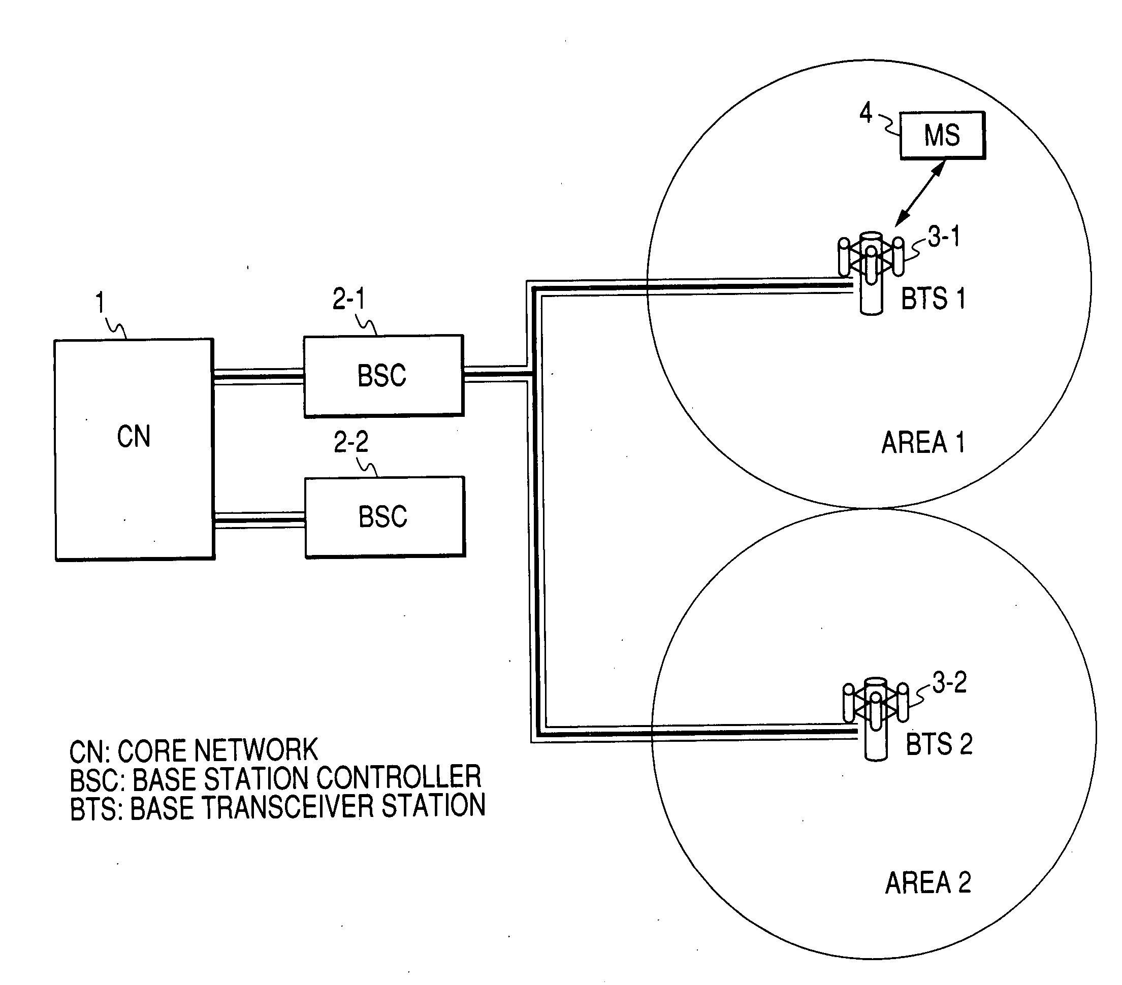
[0031]FIG. 1 shows a network configuration of a cellular communication system. A core network 1 is operable to deal with position registration and attestation and accounting services of subscriber terminals, such as cellular phones, and also perform the routing of data and audio / voice signals. A base station control device 2 is equivalent in functionality to a radio network controller (RNC) or a base station controller (BSC), for performing voice transfer rate conversion and the assignment of a radio channel to a terminal in accordance with a call-in from another terminal or a call-out from the terminal that is present in an area which is managed by the base station control device. A base station 3 corresponds to a base transceiver station (BTS), for applying encoding and modulation to the data or voice signals as sent from the base station control device 2 and for performing communication with a terminal 4 by using a radio link. Adversely, for data and voice signals as sent via a r...


PUM


Abstract

A base station apparatus is provided for adaptively controlling a maximal accommodation channel number per unit area (for example, the coverage area of a cell or sector) in accordance with a traffic quantity without relying upon detachment of a mobile base station and installation of a repeater. Upon inputting of a plurality of baseband signals of a user channel-multiplexed channel group, linear coupling is performed by a weight which is different per area that outputs it, thereby enabling control of the channel density. Additionally, a per-group available channel number is constantly monitored to control the weight while using threshold judgment for the available channel number as a trigger, thus achieving situation-sensitive prompt handleability.

Description

INCORPORATION BY REFERENCE [0001] The present application claims priority from Japanese application JP2005-043366 filed on Feb. 21, 2005, the content of which is hereby incorporated by reference into this application. BACKGROUND OF THE INVENTION [0002] The present invention relates to a base station apparatus for use in mobile communications systems. [0003] A technique for providing a mobile cellular communication system capable of eliminating communication failure states otherwise occurring due to temporal congestion is disclosed in JP-A-10-66138. This mobile communication system is such that a plurality of network-linkable fixed base stations communicate via radio channels with mobile phones existing in coverage areas of the fixed base stations, wherein the mobile communication system includes a first detector unit for detecting from among the plurality of fixed base stations a first fixed base station which presently experiences occurrence of congestion, a mobile base station whi...

Claims


Application Information

Patent Timeline
Patent Type & Authority Applications(United States)
IPC IPC(8): H04B1/38H04M1/00H04B7/06H04W76/02H04J13/00H04W16/28H04W72/04H04W76/00H04W88/08H04W92/00H04W92/12
CPCH04W72/04H04W88/08H04B7/155
Inventor FUJISHIMA, KENZABURO
Owner HITACHI LTD
Learn More