
Techniques for using first sign of life at edge nodes for a virtual private network

a virtual private network and edge node technology, applied in the field of virtual private network first sign of life technology, can solve the problems of equipment not being able to communicate over the vpn, tedious manual provisioning process, process delays,

Inactive Publication Date: 2006-08-24
CISCO TECH INC
View PDF41 Cites 46 Cited by
  • Summary
  • Abstract
  • Description
  • Claims
  • Application Information

AI Technical Summary

Benefits of technology

The patent text describes a method for using virtual private networks (VPNs) on a packet switched network (PSN) infrastructure, such as a network of routers using the Internet Protocol (IP) or using MPLS as a layer 2.5 protocol. The method involves configuring each customer interface to the provider edge network node for VPN operation without human intervention. The technical effect of this invention is to provide a more efficient and automated way of setting up and operating VPNs on a PSN infrastructure, which can save time and resources for the service provider.

Problems solved by technology

The manual provisioning process is tedious and error prone.
Furthermore, when a new piece of customer equipment is connected to an edge node, that equipment is unable to communicate over the VPN unless and until the human administrator provisions the VPN to add the new interface.
Thus the process is subject to delays.
The delays grow in severity as the human administrator becomes busier.
The tedium and propensity for error increase with the complexity of the VPN topology (e.g., as the numbers of interfaces and edge nodes increase).

Method used


Image

  • Techniques for using first sign of life at edge nodes for a virtual private network
  • Techniques for using first sign of life at edge nodes for a virtual private network
  • Techniques for using first sign of life at edge nodes for a virtual private network

Examples


embodiment 272

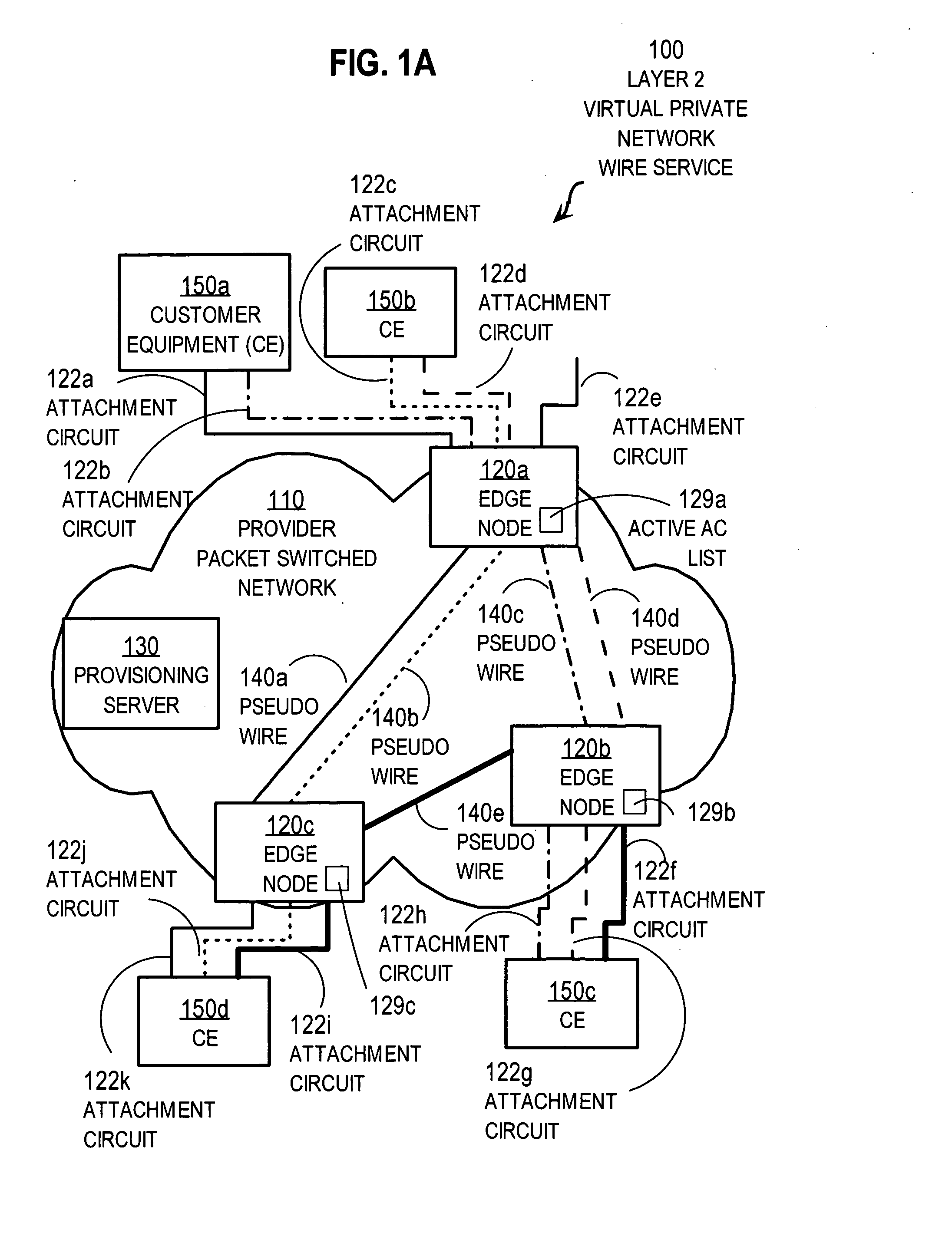
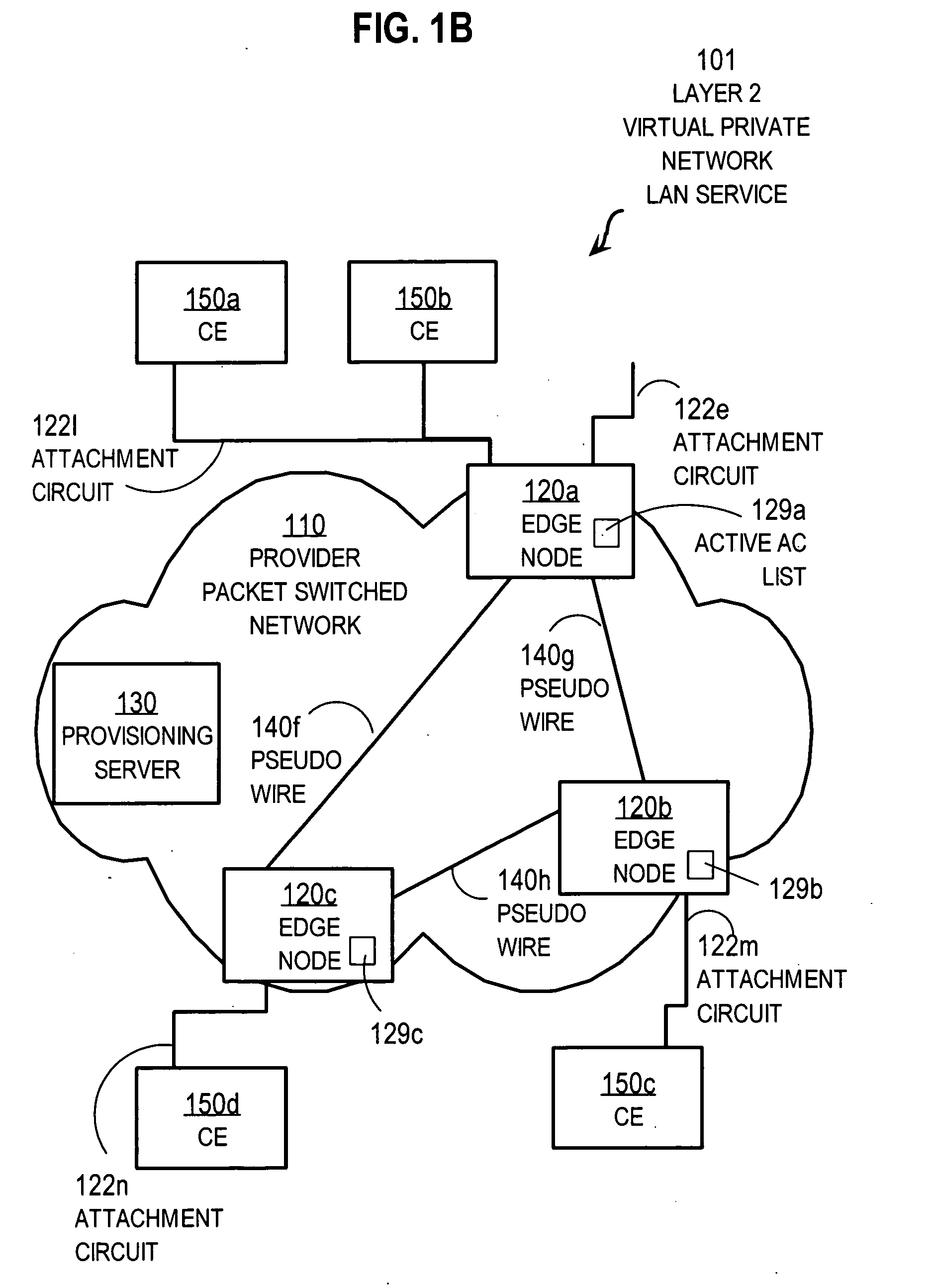
[0080]FIG. 2D is a flow diagram that illustrates step 262 of the method of FIG. 2A for obtaining configuration data for a physical port in more detail, according to an embodiment 272. Step 272 is a particular embodiment of step 262. Step 272 includes step 273 and step 275. In step 273 one or more requests are sent to one or more provisioning servers identified in step 212. The request identifies the sending node and the physical port, for example by the IP address of the sending node in the header of the request and the physical port ID number of the port. For example, a request from PE 120a for port # 4 includes a source address of 1.1.1.1 in an IP header and a physical port ID of 4, with no data indicating a particular virtual circuit.

[0081] In step 275, one or more response messages are received from one or more provisioning servers. The response messages include data that indicates: [0082] 1] one or more VPNs used by that physical port; or [0083] 2] a customer device type to be ...

embodiment 274

[0088]FIG. 2E is a flow diagram that illustrates step 264 of the method of FIG. 2A for obtaining configuration data for a virtual circuit in more detail, according to an embodiment 274. Step 274 is a particular embodiment of step 264. Step 274 includes step 277 and step 279. In step 277 one or more requests are sent to one or more provisioning servers identified in step 212. The request identifies the sending node and the virtual circuit, for example by the IP address of the sending node in the header of the request and the virtual circuit identifier. For example, a request from PE 120a for the ATM switched virtual circuit includes a source address of 1.1.1.1 in an IP header and a virtual circuit ID of “20.2.34.” Similarly, a request from PE 120a for the FR switched virtual circuit includes a source address of 1.1.1.1 in an IP header and a virtual circuit ID of “25.11.”

[0089] In step 279, one or more response messages are received from one or more provisioning servers. The response ...

embodiment 281

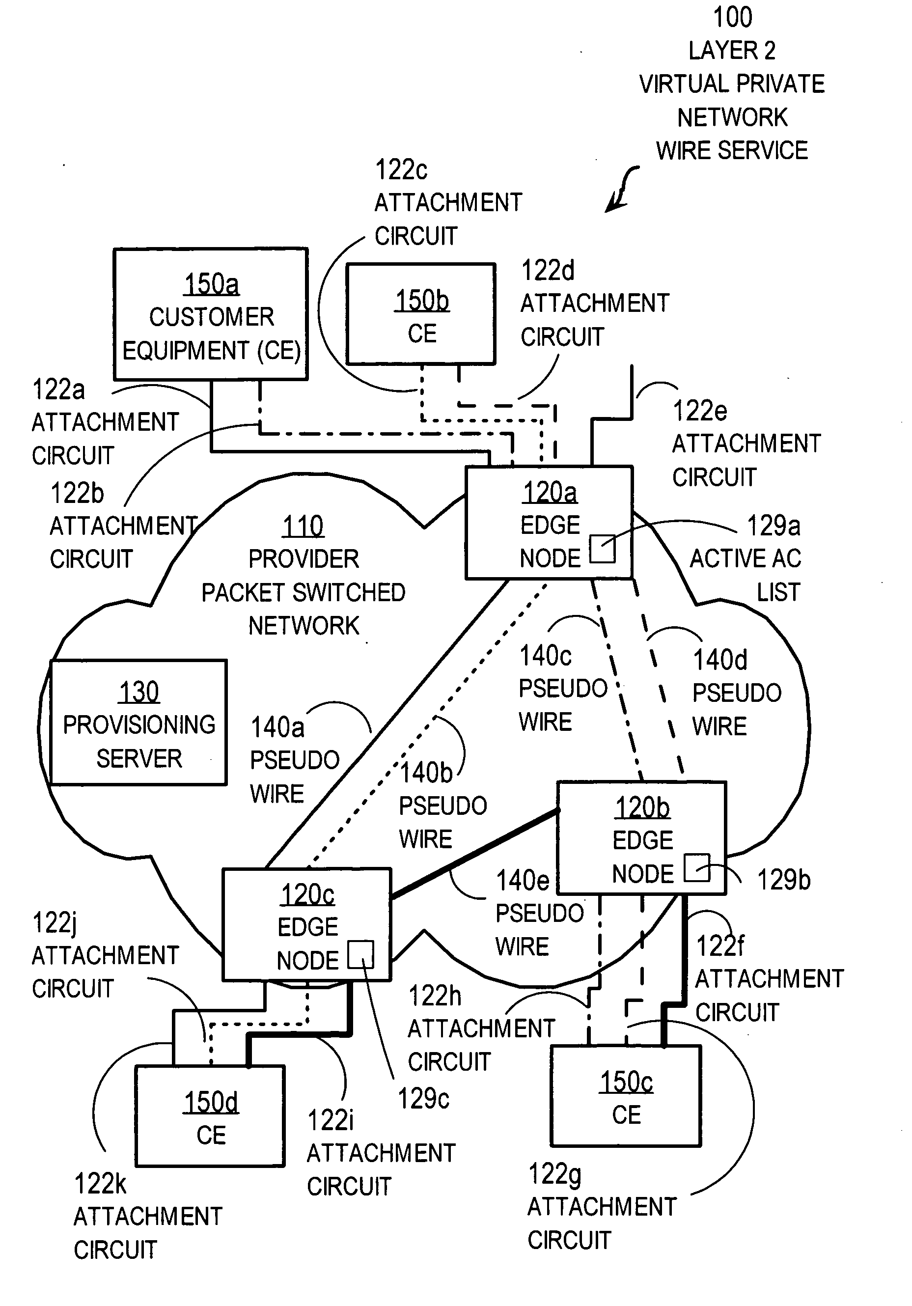
[0103]FIG. 2C is a flow diagram that illustrates step 280 of the method of FIG. 2A for responding to a FSOL based on configuration data in more detail, according to an embodiment 281. Step 281 is a particular embodiment of step 280. Step 281 includes steps 282, 284, 286, 288. In other embodiments, one or more of these steps are omitted. For example in some embodiments, step 288 is omitted. In some embodiments, step 284 is omitted. In embodiments that do not use a list of active attachment circuits, step 286 is omitted.

[0104] In step 282, it is determined whether the signal received is consistent with the configuration data retrieved. For example, it is determined whether the configuration data indicates the customer has subscribed with the provider for a VLAN “46” on port # 4, or an ATM “2.34” on port #20, or a FR “11” on port #25. If not, control passes to step 288, described below. Consistency depends upon a policy programmed into the provisioning server. In various embodiments, t...


PUM


Abstract

A method and apparatus for processing a signal on an intermediate network node at an edge of a provider packet-switched network to support a link-layer virtual private network includes receiving a signal on a particular interface. The particular interface is for a direct communication link to a customer network node outside the provider network. It is determined whether the signal indicates that the particular interface is changing from an inactive state to an active state, whereby the signal is called first sign of life (FSOL). If it is determined that the signal is FSOL, then configuration data is determined for configuring the particular interface for the particular virtual private network. The signal is processed based on the configuration data. These techniques allow a dynamic response to new signals on a customer interface without human intervention by the provider.

Description

CROSS-REFERENCE TO RELATED APPLICATIONS [0001] This application claims benefit of Provisional Appln. 60 / 654,661, filed Feb. 19, 2005, the entire contents of which are hereby incorporated by reference as if fully set forth herein, under 35 U.S.C. §119(e). [0002] This application claims benefit as a Continuation-in-part of application Ser. No. ______ (Attorney Docket No. CIS001-018), filed Jun. 1, 2005, the entire contents of which are hereby incorporated by reference as if fully set forth herein, under 35 U.S.C. §120.BACKGROUND OF THE INVENTION [0003] 1. Field of the Invention [0004] The present invention relates to using one or more virtual private networks (VPNs) based on layer 2 protocols on a packet switching infrastructure that belongs to a trusted service provider; and in particular to configuring each customer interface to a provider edge network node for VPN operation without human intervention. [0005] 2. Description of the Related Art [0006] Networks of general purpose compu...

Claims


Application Information

Patent Timeline
Patent Type & Authority Applications(United States)
IPC IPC(8): H04L12/28
CPCH04L12/4641
Inventor BOOTH, EARL HARDIN IIITOWNSLEY, WILLIAM MARKLUO, WEIWILKIE, GEORGE
Owner CISCO TECH INC
Learn More