
Spacecraft power acquisition method for wing-stowed configuration

a technology of power acquisition and spacecraft, applied in process and machine control, instruments, navigation instruments, etc., can solve the problems of increasing spacecraft weight, sensor and processor complexity, and the development cost of spacecraft attitude determination and control systems, etc., to facilitate attitude control

Active Publication Date: 2006-08-24
THE BOEING CO
View PDF11 Cites 58 Cited by
  • Summary
  • Abstract
  • Description
  • Claims
  • Application Information

AI Technical Summary

Benefits of technology

[0011] In accordance with one aspect of the invention, a method of acquiring a power-safe state for a spacecraft in a spinning transfer orbit is provided. The method includes maintaining a steady spin for a stowed solar wing configuration, sensing panel current from exposed solar panels, and synchronizing an attitude quaternion of the spacecraft with the sensed panel current to position the spin axis for power safety. The steady spin may be a z-spin or x-spin.
[0012] In accordance with another aspect of the invention, a method is provided of acquiring a power-safe state for a wing-stowed spacecraft, with one or more exposed solar panels in a spinning transfer orbit. The method includes a first rotation phase that includes maintaining a steady spin about a first axis that is substantially orthogonal to a direction that is normal to at least one of the exposed solar panels, sensing panel current from at least one of the exposed solar panels, and if the sensed solar panel peak current does not exceed a threshold current, stopping the first rotation at the peak current of one of the solar panels. The method may further include entering a second rotation phase, the second rotation phase including maintaining a steady spin about a second axis that is substantially orthogonal to the direction that is normal to at least one of the exposed solar panels, and that is substantially orthogonal to the first axis, and sensing panel current from at least one of the exposed solar panels, and if the sensed solar panel peak current does not exceed a threshold current, stopping the second rotation at the peak current of one of the solar panels, and entering the first rotation phase. The first axis may be the z-axis of the spacecraft, and the second axis may be the x-axis of the spacecraft. The first rotation phase and the second rotation phase may use thrusters and/or reaction wheels for attitude control. The first rotation and the second rotation may select a rotation direction and a rotation rate such that the reaction wheels will not be saturated. The first rotation phase and the second rotation phase may use thrusters to dump momentum to facilitate attitude control by the reaction wheels. The peak current may be determined by a peak current finding algorithm. Stopping the rotation at peak current may be performed by resetting the commanded and estimated attitude quaternions to identity at peak current.
[0013] In accordance with another aspect of the invention, a method of acquiring a power-safe attitude for a wing-stowed spacecraft in a spinning transfer orbit that has one or more exposed solar panels is provided. The met

Problems solved by technology

The use of different sensors, attitude determination, and attitude control methods for spinning transfer orbits and on-station operations, respectively, increases the spacecraft weight, sensor and processor complexity, as well as the development cost for spacecraft attitude determination and control systems.
Thus, the sensors used for transfer orbit operations may lie dormant for the entire time that the spacecraft is on station.
The number of sensor types used and the number of sensors used, increase the hardware and development cost, increase weight and launch cost, and complicate the mission operation.
In addition, some spacecraft have configurations and equipment that may make it difficult in some situations to provide a clear field of view for some sensors, such as, for example, a WFOV SSA, which spans a diamond of about 120×120 deg.

Method used


Image

  • Spacecraft power acquisition method for wing-stowed configuration
  • Spacecraft power acquisition method for wing-stowed configuration
  • Spacecraft power acquisition method for wing-stowed configuration

Examples


Embodiment Construction

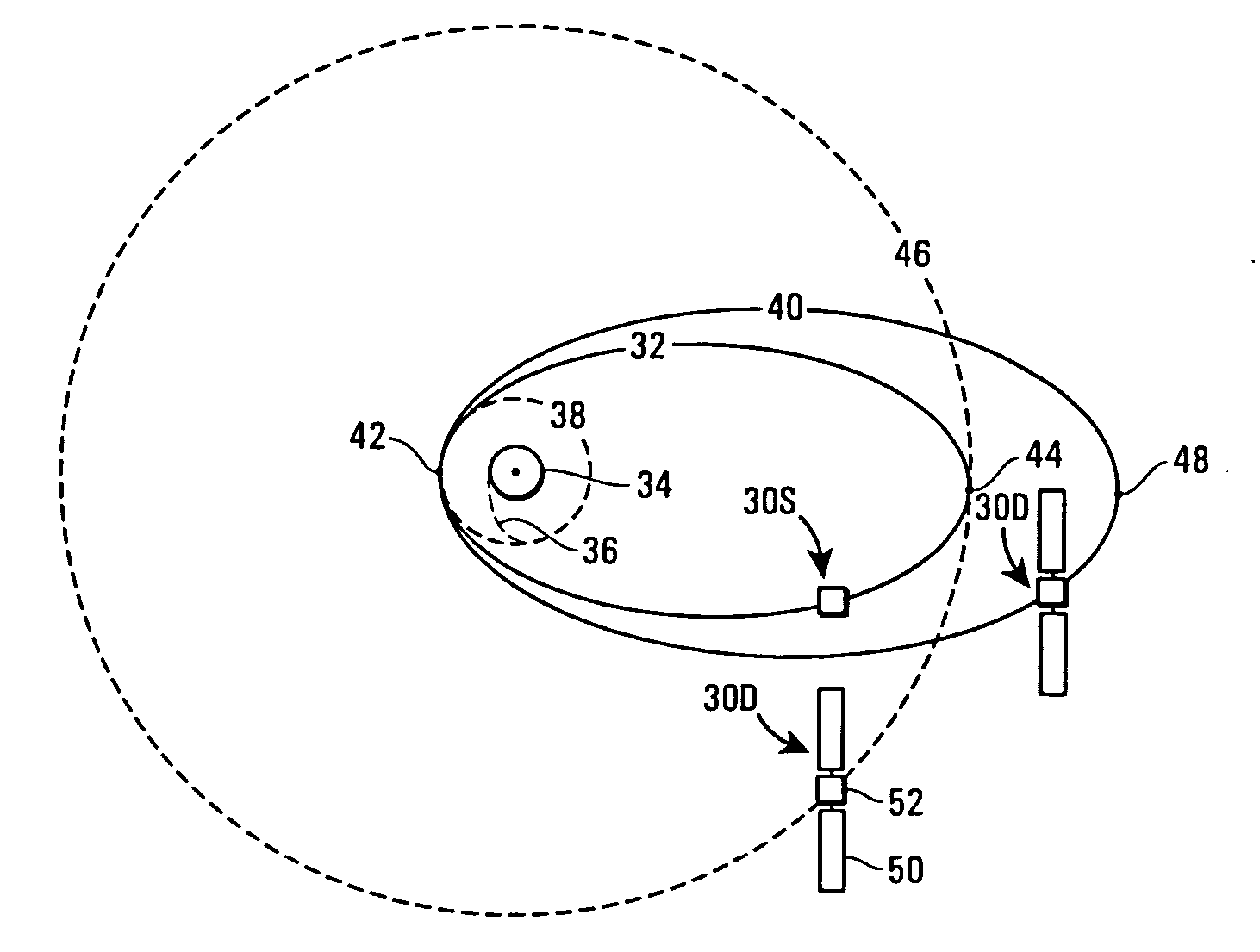
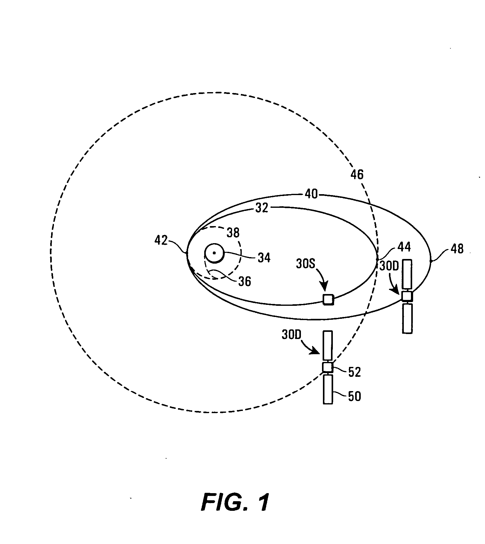
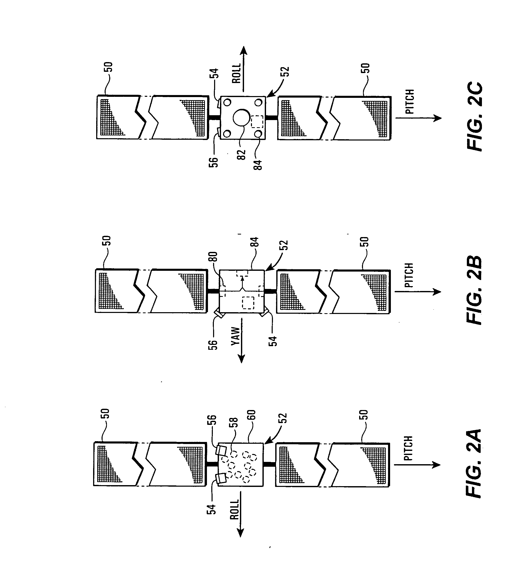
[0033] With reference initially to FIG. 1, a spacecraft 30S with its solar wings in a stowed position is depicted in a first transfer orbit 32 about the earth 34. Also depicted in FIG. 1 are a launch path 36, a parking orbit 38, and a second transfer orbit 40. The first transfer orbit 32, the parking orbit 38, and the second transfer orbit 40 may all have a common perigee point indicated at 42. The first transfer orbit 32 shares an apogee point indicated at 44, that is the same altitude as a geosynchronous orbit at 46. The second transfer orbit 40 has an apogee at 48 that is greater in altitude than the geosynchronous orbit 46. As indicated by the reference numeral 30D, the spacecraft in the second transfer orbit and in the geosynchronous orbit 46 may have solar wings 50 deployed and extending beyond a main portion 52 of the spacecraft 30D. As shown in FIGS. 2A-2C, the spacecraft 30D may include a primary star tracker 54 and a redundant star tracker 56, an optional gyro device, such...


PUM


Abstract

A system for, and method of recovering a solar-powered spacecraft from an anomaly that renders the attitude of the spacecraft unknown includes maintaining a power-safe attitude by switching between two orthogonal axes using solar panel current sensors. The system and method may also include simultaneously determining spacecraft attitude using a star sensor. The system is applicable to spacecraft operating in a solar wing-stowed configuration.

Description

CROSS REFERENCE TO RELATED APPLICATIONS [0001] This application is a continuation-in-part of U.S. patent application Ser. No. 10 / 910,430, entitled, “STAR-TRACKER-BASED ATTITUDE DETERMINATION FOR SPINNING SPACECRAFT,” filed on Aug. 3, 2004, which is in turn a continuation-in-part of U.S. patent application Ser. No. 10 / 727,764, entitled, “UNIFIED SENSOR-BASED ATTITUDE DETERMINATION AND CONTROL FOR SPACECRAFT OPERATIONS,” filed on Dec. 3, 2003, both of which are owned by the assignee of the present application, and the entirety of both of which are hereby expressly incorporated by reference herein.BACKGROUND OF THE INVENTION [0002] 1. Field of the Invention [0003] This invention is generally directed to satellite attitude and power acquisition systems and methods, and, more particularly, to satellite attitude and power acquisition systems and methods that are applicable to satellites in a solar wing-stowed configuration. [0004] 2. Description of the Related Art [0005] Transporting a sp...

Claims


Application Information

Patent Timeline
IPC IPC(8): B64G1/10B64G1/00B64G1/24B64G1/26B64G1/28B64G1/36B64G1/40B64G1/44G01C21/02G05D1/08
CPCB64G1/007B64G1/242B64G1/26B64G1/28B64G1/281B64G1/283B64G1/285B64G1/288B64G1/36B64G1/361B64G1/363B64G1/401B64G1/405B64G1/44B64G1/443G01C21/025G05D1/0883B64G1/244B64G1/369B64G1/2427
Inventor WANG, H. GRANTLI, RONGSHENG
Owner THE BOEING CO
Learn More