Fluid change system

a technology of fluid change system and fluid, which is applied in the direction of liquid handling, machines/engines, packaging goods types, etc., can solve the problems of contaminating the environment with used oil, and being susceptible to the same problems, so as to prevent the contamination of the environment and facilitate the connection/disconnect

Inactive Publication Date: 2006-08-24
FLUIDTRAN
View PDF10 Cites 0 Cited by
  • Summary
  • Abstract
  • Description
  • Claims
  • Application Information

AI Technical Summary

Benefits of technology

[0007] A principal object and advantage of the present invention is that it completely compartmentalizes fluids, preventing contamination of the environment.
[0008] Another principal object and advantage of the present invention is that if provides a quick connect / disconnect between two components.
[0009] Another principal object and advantage of the present invention is that it provides a quick connect / disconnect for both old fluid removal and new fluid insertion.

Problems solved by technology

However, most oil change systems are prone to contaminating the environment with used oil.
This becomes a severe problem when a great deal of oil change activity occurs at a particular location, such as a car rental fleet facilities or an airline maintenance facility.
Similar problems arise when changing other engine fluids such as transmission fluids and coolants.
Portable oil change systems are also known, but are generally susceptible to the same problems.

Method used


Image

  • Fluid change system
  • Fluid change system
  • Fluid change system

Examples


Embodiment Construction

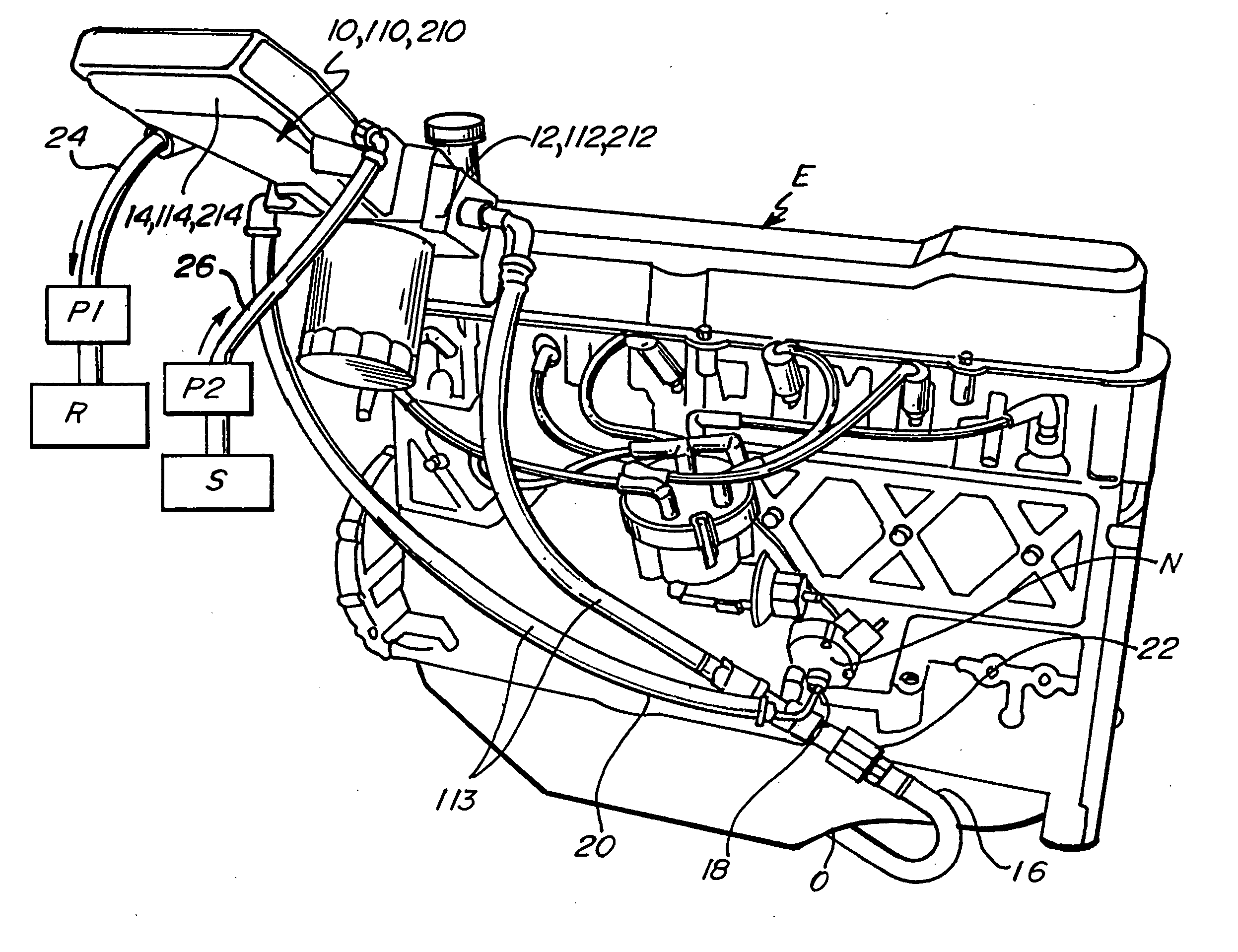
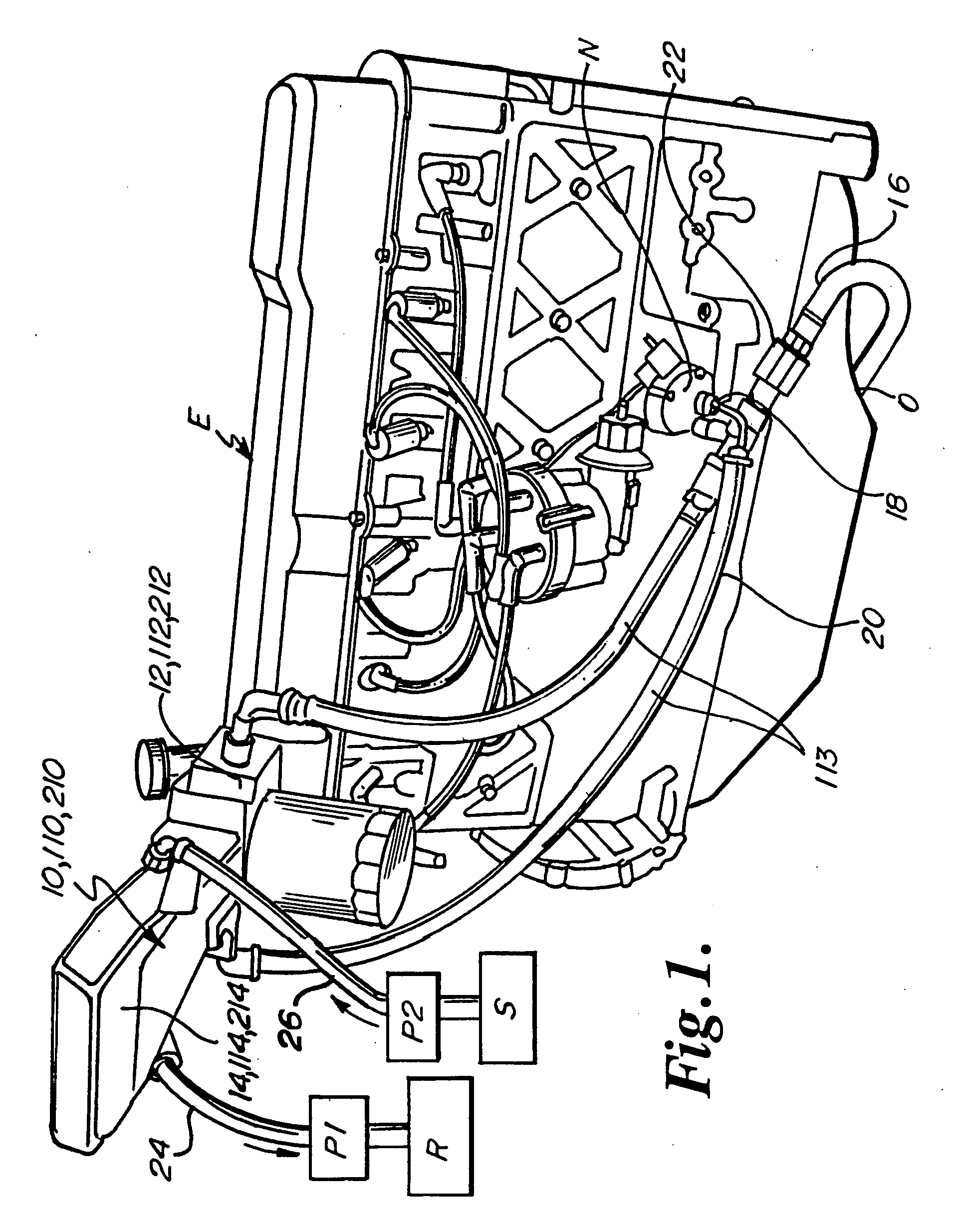
[0017] The fluid change apparatus of the present invention is generally shown in the Figures as reference numerals 10, 110, 210.

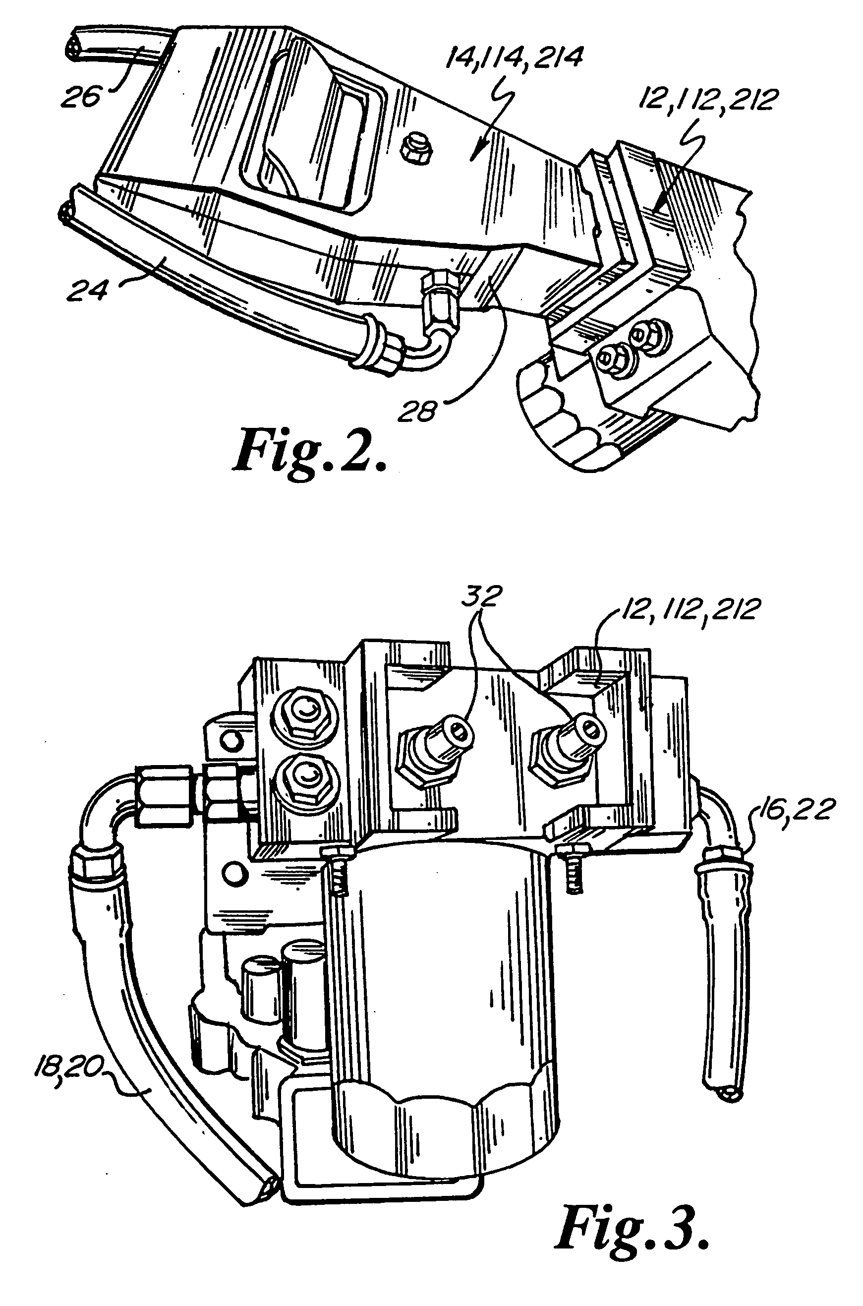
[0018] In one aspect (FIG. 1), the apparatus 10 comprises a first portion 12 adapted to be connected to an engine E and a second portion 14 mating with the first portion 12 and adapted to be connected to a source S of new fluid and to a receptacle R for old fluid.

[0019] Preferably, the first portion 12 is adapted to be connected to the engine by a first connection 16 to remove old fluid from the engine and by a second connection 18 to insert new fluid into the engine. Preferably, the first connection 16 and second connection 18 comprise hoses 20 and couplers 22.

[0020] Preferably, the second portion 14 is adapted to be connected to the receptacle R for old fluid by a third connection 24 to transfer old fluid to the receptacle R and is adapted to be connected to the source of new fluid S by a fourth connection 26 to transfer new fluid from the source S. Pr...


PUM

PropertyMeasurementUnit
internal structureaaaaaaaaaa

Abstract

A fluid change apparatus consisting of two components. One component is associated with the engine and the other component is associated with a source of new fluid and a receptacle for old fluid. The present invention provides a fast connection between the two components that completely compartmentalizes the fluids.

Description

BACKGROUND OF THE INVENTION [0001] The present invention is directed to a fluid change apparatus for removing used fluid from an engine and inserting new fluid into the engine. In particular, the present invention is directed to a fluid change apparatus that removes used fluid from the engine and inserts new fluid into the engine while compartmentalizing the fluids and preventing contamination of the environment. [0002] Oil change systems for engines are known in the art. However, most oil change systems are prone to contaminating the environment with used oil. This becomes a severe problem when a great deal of oil change activity occurs at a particular location, such as a car rental fleet facilities or an airline maintenance facility. Similar problems arise when changing other engine fluids such as transmission fluids and coolants. Portable oil change systems are also known, but are generally susceptible to the same problems. [0003] In high-use facilities such as car rental fleet f...

Claims


Application Information

Patent Timeline
Patent Type & Authority Applications(United States)
IPC IPC(8): B65B3/04
CPCF01M11/0458
Inventor BENSON, ROBERT D.
Owner FLUIDTRAN
Why Eureka
Try Eureka