
Method for controlling air conditioning system

a technology for controlling an air conditioning system and a control method, which is applied in the direction of heating types, instruments, and static/dynamic balance measurement, etc., can solve the problems of limiting the effective control the limitation of the resolution of the unpleasant feeling of the people in the room, and the limitation of the effect of the air conditioning system

Inactive Publication Date: 2006-08-17
LG ELECTRONICS INC
View PDF5 Cites 29 Cited by
  • Summary
  • Abstract
  • Description
  • Claims
  • Application Information

AI Technical Summary

Benefits of technology

[0020] An object of the present invention is to provide a method for controlling an air conditioning system for improving an air conditioning performance and IAQ taking a room environment into account to the maximum.

Problems solved by technology

In general, the increase of a carbon dioxide content of air in a closed room as time passes-by by respiration of people in the room, and the rapid increase of heat load of an office caused by office automation and concentration coming from high land price causes unpleasant feeling of the people in the room.
However, there has been a limitation in effective control of the air conditioning system by taking all correlation between a human heat sense and physical environments, such as a room temperature, humidity, air flow speed, a radiation temperature into account.
However, the related art air conditioning system has the following problem.
First, there has been a limitation in resolution of an unpleasant feeling the people in the room have, and providing a higher comfort to the people in the room, only by application of the PMV and the PPD.
Second, if the air conditioning system fails to sense the sensitive room environment properly, the people in the room are liable to live in the unpleasant environment.

Method used


Image

  • Method for controlling air conditioning system
  • Method for controlling air conditioning system
  • Method for controlling air conditioning system

Examples


Embodiment Construction

[0037] Reference will now be made in detail to the preferred embodiments of the present invention, examples of which are illustrated in the accompanying drawings. Wherever possible, the same reference numbers will be used throughout the drawings to refer to the same or like parts.

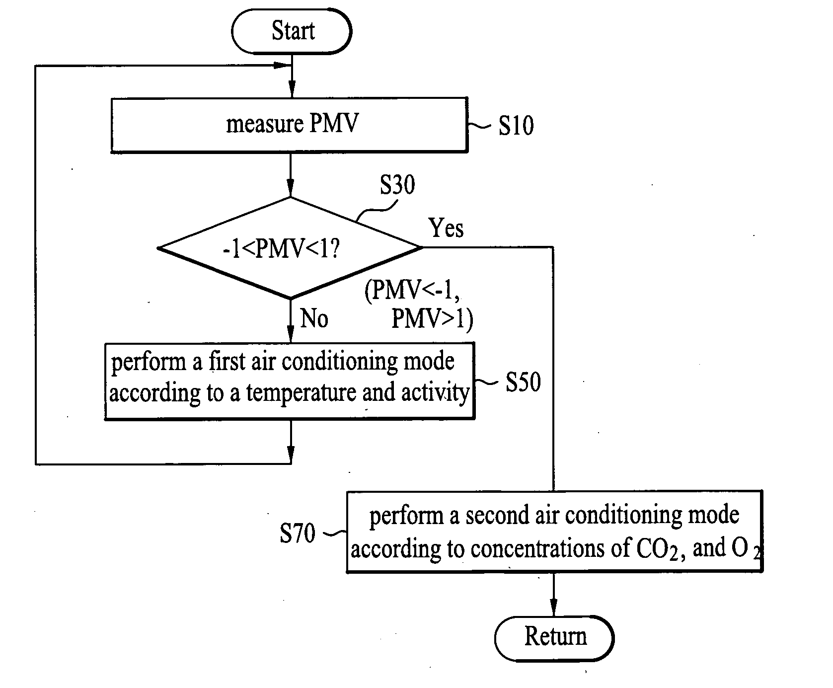
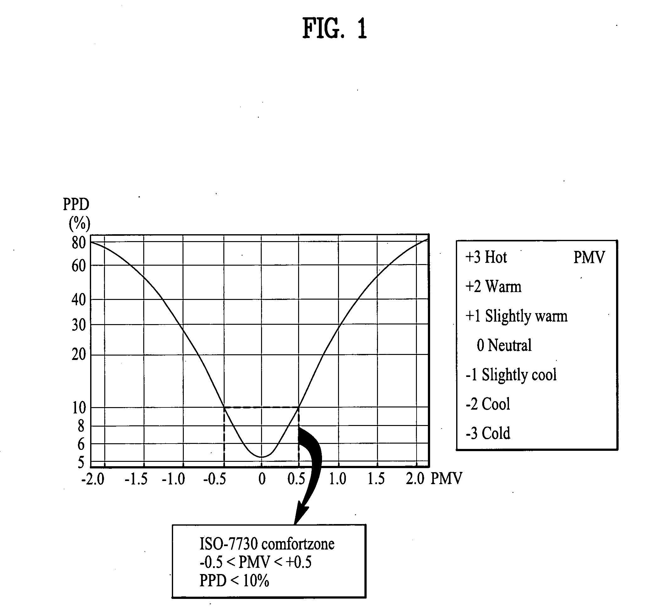
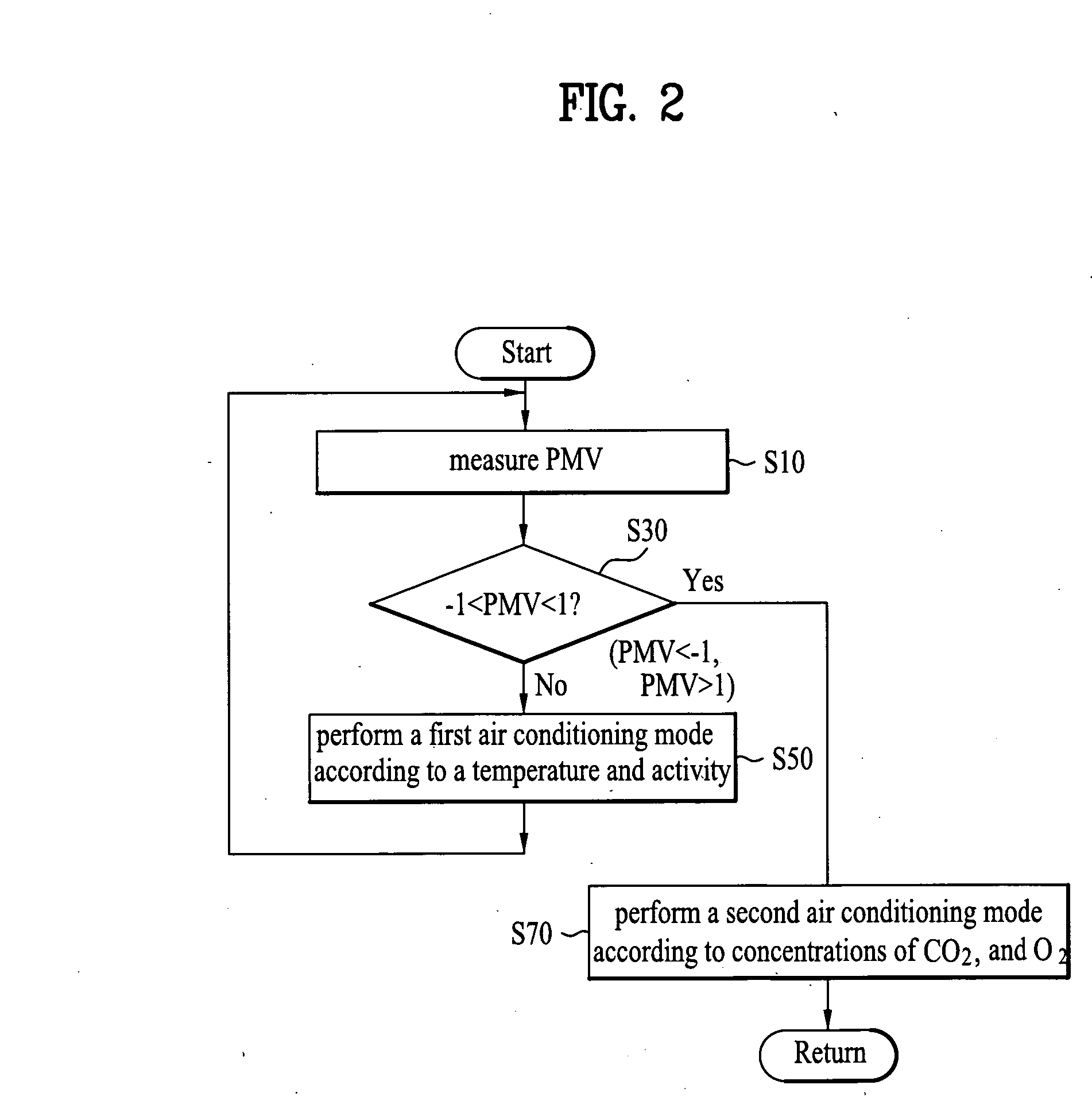
[0038] At first, the air conditioning system of the present invention measures the present PMV of a room from thermal environment parameters of human being, and environment of an air temperature, humidity, an air flow speed, a mean radiation temperature, a wearing clothes amount, and an activity amount.

[0039] To do this, the air conditioning system of the present invention includes 6 kinds of sensing means which can measure the six kinds of thermal environmental parameters.

[0040] For an example, the room temperature can be measured with a temperature sensor, and a mean radiation temperature can be calculated by using the room temperature detected at the temperature sensor.

[0041] Moreover, the relative h...


PUM


Abstract

Method for controlling an air conditioning system including the steps of measuring a Predicted Mean Vote (PMV) according to thermal environmental parameters of a room, performing a first air conditioning mode if the PMV falls outside of a preset allowable range, for controlling an air flow speed and a room temperature, and performing a second air conditioning mode if the PMV falls within the allowable range, for controlling ventilation and air cleaning operation, whereby improving the IAQ (Indoor Air Quality) further by enhancing the PPIS by performing air conditioning so that the PMV reaches to an optimum range, and then, by generating active materials (oxygen / terpene).

Description

CROSS-REFERENCE TO RELATED APPLICATION [0001] This application claims the benefit of Korean Application No. P2005-0012308 filed on Feb. 15, 2005, which is hereby incorporated by reference as if fully set forth herein. BACKGROUND OF THE INVENTION [0002] 1. Field of the Invention [0003] The present invention relates to air conditioners, and more particularly, to a method for controlling an air conditioning system for improving an IAQ (Indoor Air Quality). [0004] 2. Discussion of the Related Art [0005] Recently, people pass around 80% of one day in room spaces, such as houses, offices, and underground spaces. With regard to the people who pass most of their time in room spaces, a comfortable room environment can enhance efficiency of their work, and, moreover, is very important for maintaining their health. [0006] Particularly, as living standards of people become the higher, demands for the comfortable room space of the people become the higher. [0007] In general, the increase of a ca...

Claims


Application Information

Patent Timeline
Patent Type & Authority Applications(United States)
IPC IPC(8): G05D23/00
CPCF24F11/0012F24F11/0017F24F2003/1692Y02B30/78F24F2011/0028F24F2011/0064F24F2011/0026F24F11/30F24F2110/10F24F2110/50F24F2110/70F24F2110/76F24F11/65F24F8/60Y02B30/70F24F11/77F24F11/62F24F11/49F24F2110/20F24F2110/30Y02B30/90
Inventor LEE, JU YOUNCHOI, HO SEON
Owner LG ELECTRONICS INC
Learn More