Mode door for the automotive vehicle air conditioning system

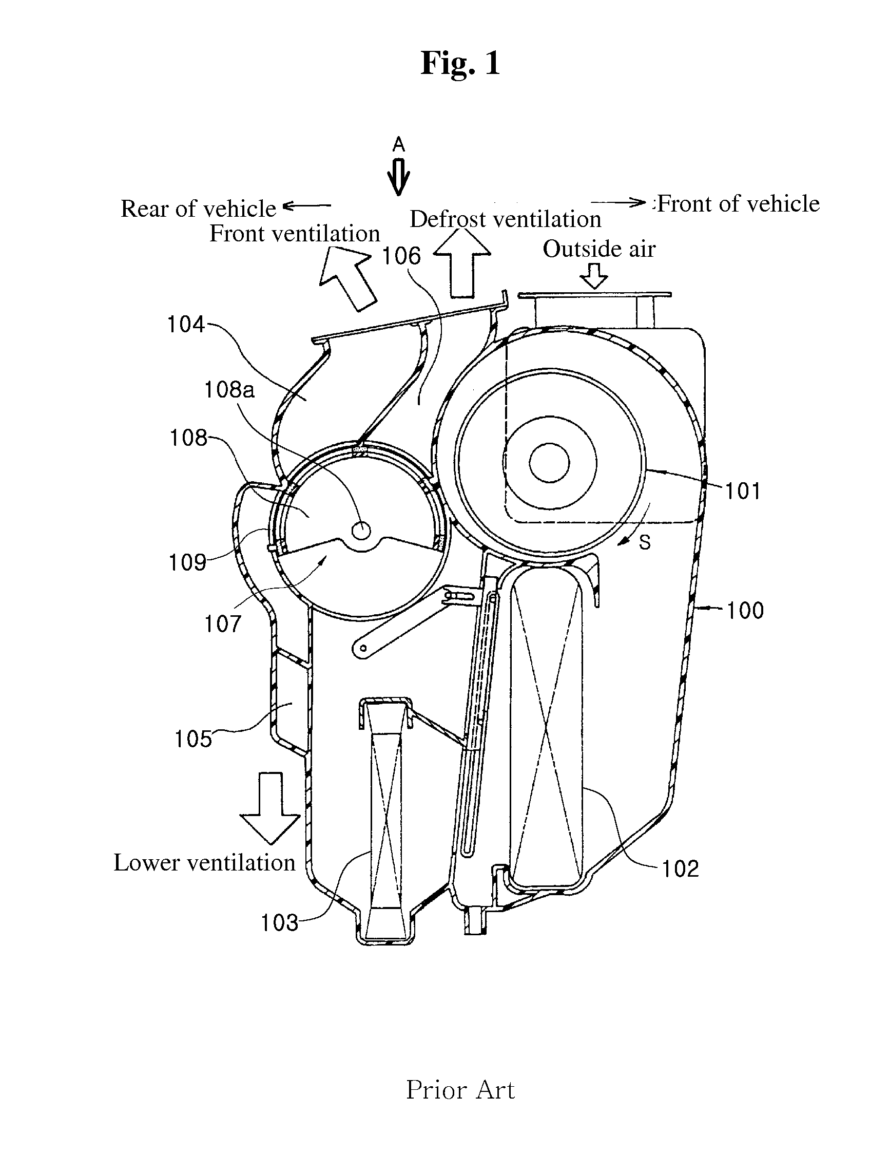
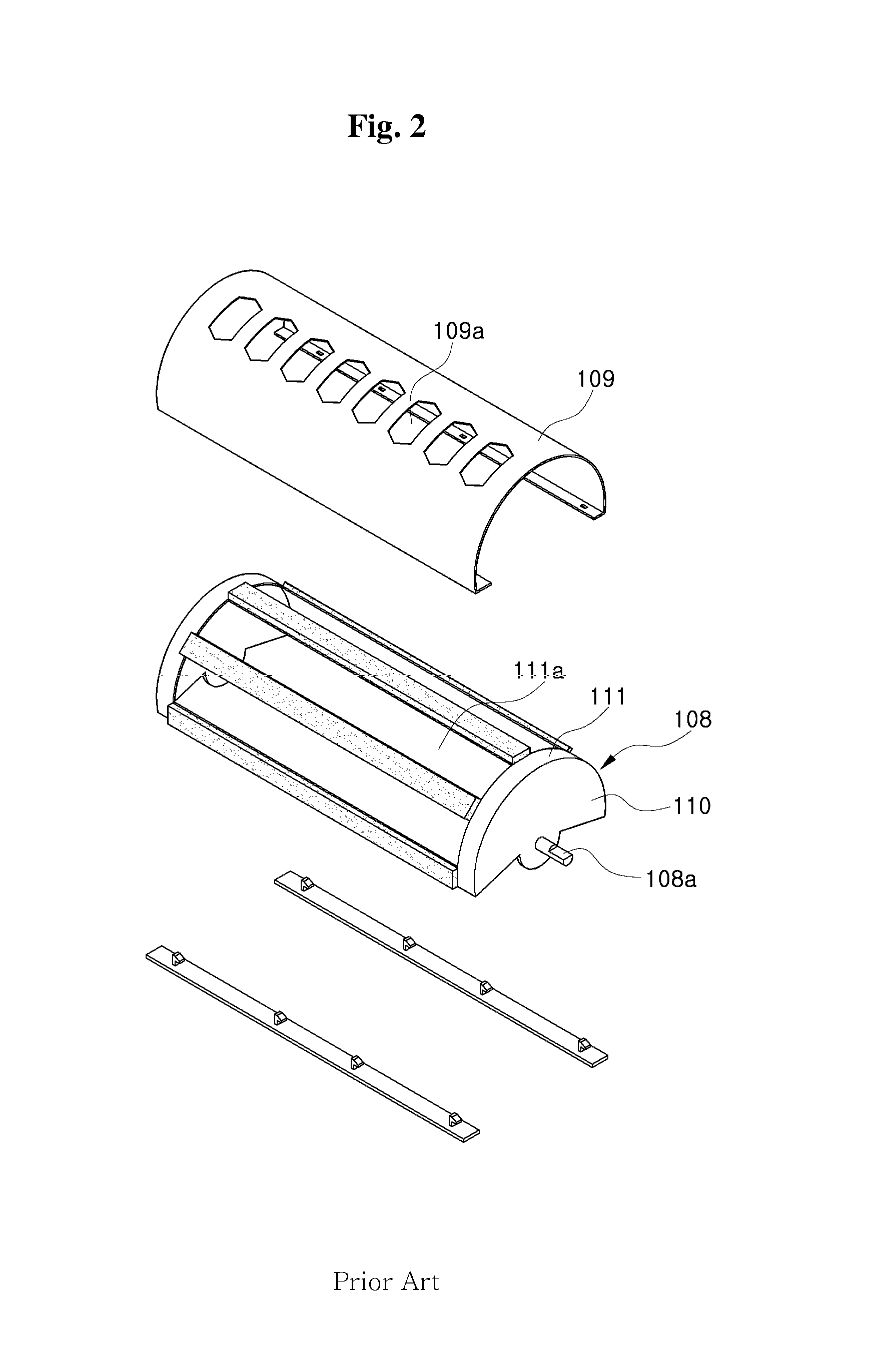
a technology for automobiles and air conditioners, which is applied in vehicle heating/cooling devices, transportation and packaging, and light and heating apparatus, etc. it can solve the problems of noise generation, complicated assembly of cylindrical doors b>107/b>, and increased costs associated with the manufacture of air conditioning cases. achieve the effect of improving air conditioning performan

Active Publication Date: 2010-08-03
HANON SYST
View PDF10 Cites 10 Cited by
  • Summary
  • Abstract
  • Description
  • Claims
  • Application Information

AI Technical Summary

Benefits of technology

[0025]Accordingly, the present invention has been made in an effort to solve the above problems of the prior art. It is an object of the present invention to provide an air conditioning system for automobiles in which air introduced into an air conditioning case is always discharged to both sides of the passenger compartment of a vehicle regardless of the specific mode while the air conditioning system is maintaining the amount of air discharged through defrost openings in a defrost mode, and in which leakage of air between both sides of a mode door and the air conditioning case is effectively prevented without requiring an additional sealing process to thereby improve air conditioning performance.

Problems solved by technology

This, in turn, causes the generation of noise.
In addition, it is necessary to perform an additional sealing process during production of the cylindrical door 107 such that costs associated with the manufacture of the air conditioning case 100 are increased and assembly of the cylindrical door 107 and the air conditioning case is made complicated.

Method used


Image

  • Mode door for the automotive vehicle air conditioning system
  • Mode door for the automotive vehicle air conditioning system
  • Mode door for the automotive vehicle air conditioning system

Examples


third embodiment

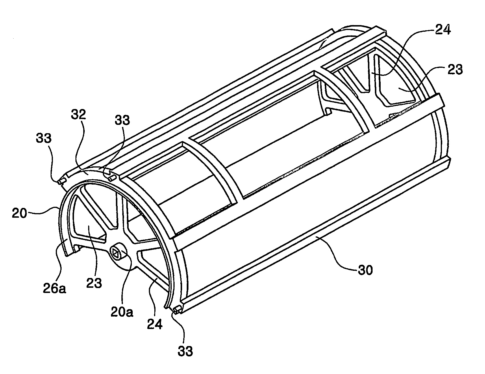
[0077]FIG. 14 is a sectional view showing a structure of air leakage preventing means 60 according to the present invention.

[0078]A structure is used in this embodiment that is opposite the structure used in the first and second embodiments. In particular, grooves 26c are formed in the side surfaces 26 of the rotating door 20 and protrusions 10c that are received in the grooves 26c are formed in opposing surfaces of the air conditioning case 10. It is possible also to add additional grooves 26c and protrusions 10c respectively in the rotating door 20 and the air conditioning case 10.

fourth embodiment

[0079]FIG. 15 is a sectional view showing a structure of air leakage preventing means 70 according to the present invention.

[0080]In this embodiment, a stepped portion 26d is formed in each of the side surfaces 26 of the rotating door 20, and grooves 10d are formed in opposing surfaces of the air conditioning case to receive the stepped portions 26d. Additional stepped portions 26d and grooves 10d may be formed respectively in the rotating door 20 and the air conditioning case 10.

fifth embodiment

[0081]FIG. 16 is a sectional view showing a structure of air leakage preventing means 80 according to the present invention.

[0082]A structure is used in this embodiment that is opposite the structure used in the fourth embodiment. In particular, grooves 26e are formed in the side surfaces 26 of the rotating door 20 and stepped portions 10e that are received in the grooves 26e are formed in opposing surfaces of the air conditioning case 10. It is possible also to add additional grooves 26e and stepped portions 10e respectively in the rotating door 20 and the air conditioning case 10.

[0083]The elements forming the above air leakage preventing means of the protrusions 10c, 26a, and 26b, the grooves 10a, 10b, 10d, 26c, and 26e, and the stepped portions 10d, 10e, and 26d are continuously formed along a rotational direction of the mode door.

[0084]Operation of the air conditioning system for automotive vehicles of the embodiments of the present invention that has the structure as described...


PUM


Abstract

An automotive vehicle air conditioning system has air introduced into an air conditioning case. The introduced air is always discharged to both sides of a passenger compartment regardless of the air conditioner mode while the air conditioning system maintains the amount of air discharged through defrost openings in a defrost mode. Air leakage between both sides of a mode door and the air conditioning case is effectively prevented by a cover carried by the mode door without additional sealing to improve air conditioning performance.

Description

CROSS-REFERENCE TO RELATED APPLICATIONS[0001]This is a U.S. National Phase PCT application and claims the benefit of the filing date of PCT / KR2004 / 000024, filed Jan. 9, 2004, and also claims the benefit of priority under 35 U.S.C. §119 of Korean Application Nos. 10-2003-0001832, filed Jan. 11, 2003; 10-2003-0033363, filed May 26, 2003; and 10-2003-0040185, filed Jun. 20, 2003, the entire disclosures of which are hereby herein incorporated by reference.TECHNICAL FIELD[0002]The present invention relates to an air conditioning system for automobiles, and more particularly, to an air conditioning system for automobiles in which air introduced into an air conditioning case is always discharged to both sides of the passenger compartment of a vehicle regardless of the specific mode while the air conditioning system is maintaining the amount of air discharged through defrost openings in a defrost mode, and in which leakage of air between both sides of a mode door and the air conditioning ca...

Claims


Application Information

Patent Timeline
Patent Type & Authority Patents(United States)
IPC IPC(8): B60H1/00F28F27/00B60H3/00F28F27/02
CPCB60H1/00685B60H2001/007
Inventor KIM, JONG-SULEE, DAE-WOONG
Owner HANON SYST
Why Eureka
Try Eureka